Reference material
System, operating and application references from the source catalogue. Model-specific ratings are given in the specification table.
Servo press system features
2024 actuator catalogue, p. 76
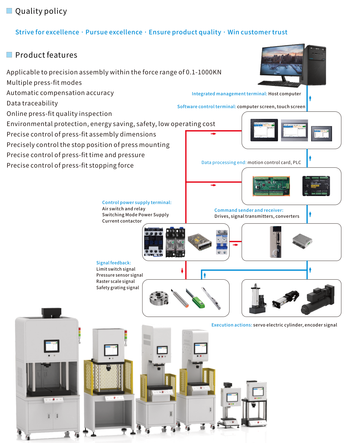
Applicable to precision assembly within the force range of 0.1-1000KN. Multiple press-fit modes; automatic compensation accuracy; data traceability; online press-fit quality inspection. The catalogue describes control of press-fit assembly dimensions, stopping position, time and pressure, and stopping force.
System overview.
Source illustration
Control architecture
2024 actuator catalogue, p. 76
Integrated management terminal: host computer. Software control terminal: computer screen or touch screen. Data processing end: motion control card or PLC. Command sender and receiver: drives, signal transmitters and converters. Execution actions: servo electric cylinder and encoder signal.
The control power supply terminal includes an air switch, relay, switching-mode power supply and current contactor. Signal feedback includes limit switches, pressure sensors, raster scale and safety grating signals.
System functions and overview
2024 actuator catalogue, p. 77
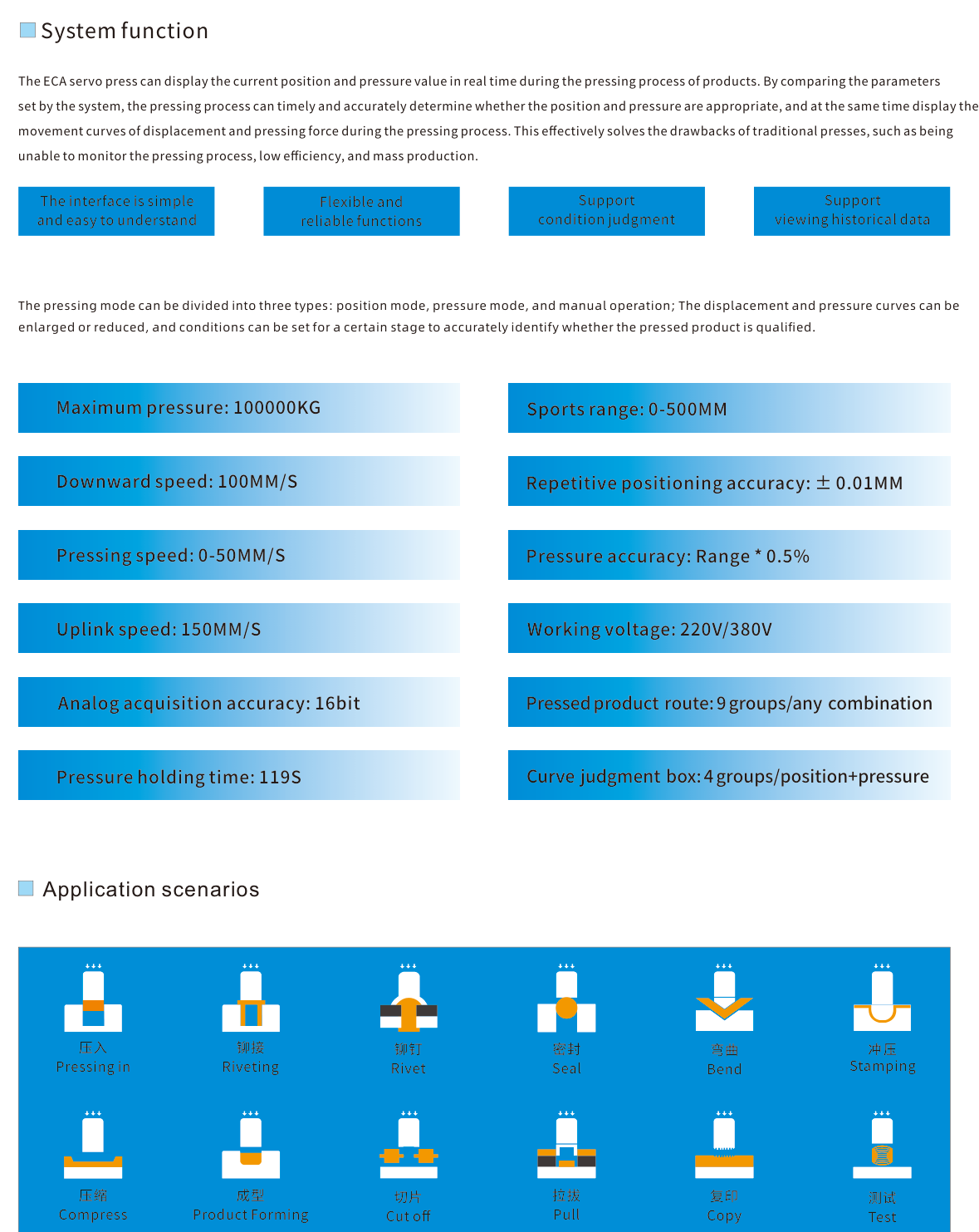
The system displays position and pressure during pressing, compares them with configured parameters, and displays displacement and pressing-force curves. The pressing mode can be position mode, pressure mode or manual operation. Curves can be enlarged or reduced; a condition can be set for a particular stage. Historical data can be viewed.
The overview boxes print: maximum pressure 100000KG; sports range 0-500MM; downward speed 100MM/S; pressing speed 0-50MM/S; uplink speed 150MM/S; repetitive positioning accuracy ±0.01MM; pressure accuracy Range * 0.5%; working voltage 220V/380V; analog acquisition accuracy 16bit; pressed product route 9 groups/any combination; pressure holding time 119S; curve judgment box 4 groups/position+pressure.
System overview figures.
Source illustration
Example processes
2024 actuator catalogue, p. 77
The catalogue illustrates pressing in, riveting, rivet, seal, bend, stamping, compress, product forming, cut off, pull, copy and test operations.
Home and external monitoring
2024 actuator catalogue, p. 78
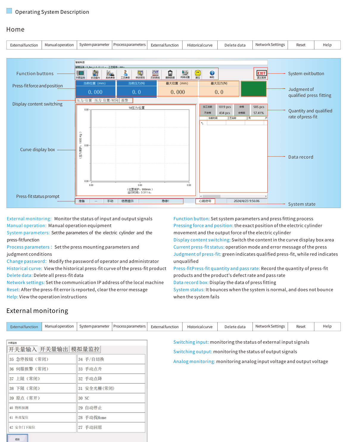
The Home view identifies function buttons, press-fit force and position, display-content switching, the curve display box, press-fit status prompt, system exit, press-fitting judgment, quantity and qualified rate, data record and system state.
External monitoring shows input and output signal status, including switching-input, switching-output and analog-input voltage monitoring. Manual operation controls the equipment manually. System parameters set the electric-cylinder and press-function parameters. Process parameters set press mounting parameters and judgment conditions. Other functions include changing operator/administrator passwords, historical curves, deleting press-fit data, local-machine communication IP address, clearing an error message after an error, and operating help.
The display-content switch changes the curve display area. Press-fitting quantity/pass-rate counters and data records provide process records; the system state reports whether the system is normal.
Source illustration
Manual operation and system settings
2024 actuator catalogue, p. 79
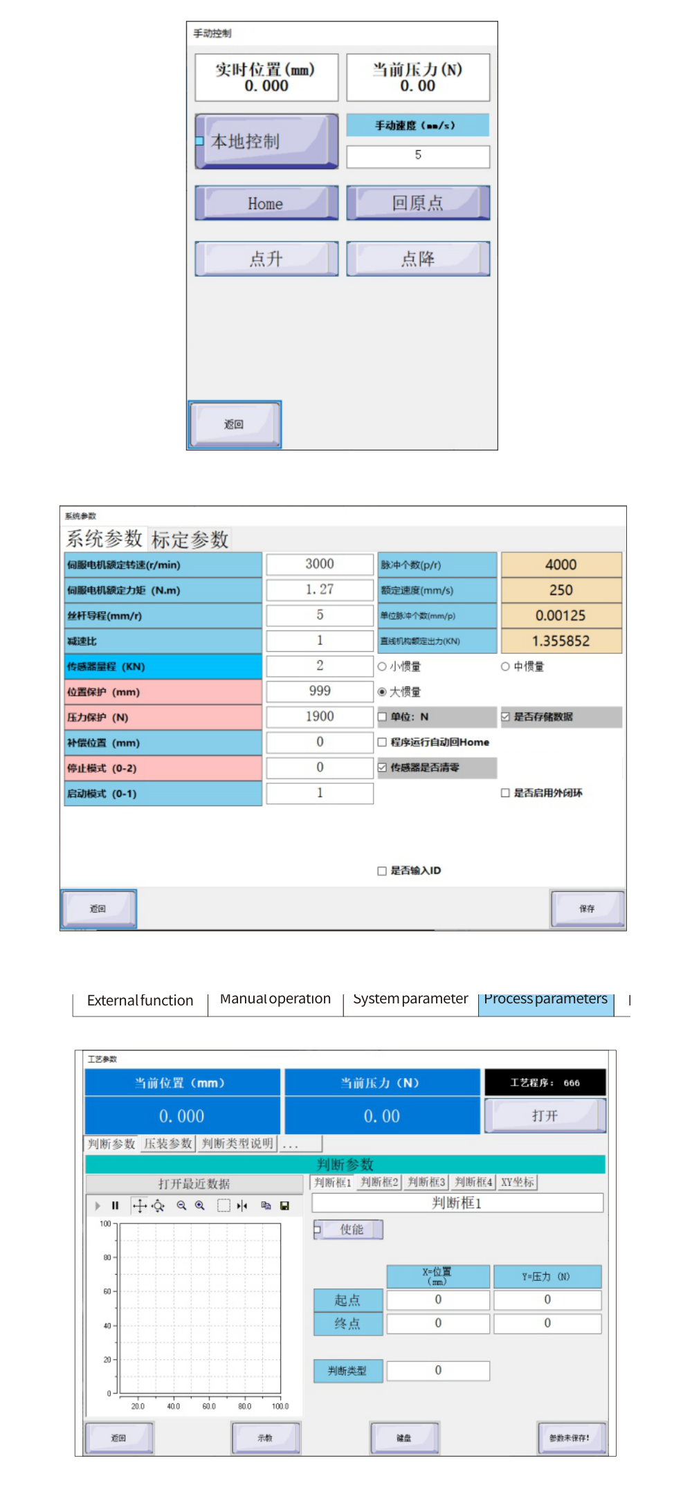
Manual control requires local control and selection of manual mode with the external automatic/manual mechanical switches. Homing and pressure-zero reset appear in the source interface. The catalogue excerpt does not specify the emergency-stop interlock state for homing. Return to Origin uses the origin position set in the process parameters.
System parameters are set at the factory. The source describes inertia adjustment for the pressure-holding process; compensation position for testing distance; stop modes (press the entire process, error stop, or return to origin after an error); single- or double-button start; KG/N unit switching; saving data; sensor reset after Home; external closed-loop displacement-scale correction; and serial-port communication with an external upper computer.
Source illustration
Process parameter reference
2024 actuator catalogue, p. 79
Open selects a saved process-parameter file. Judgment parameters add press-fit conditions, enabled with a checkbox; up to four sets of pressure and position conditions can be set. XY coordinates define the beginning and ending positions of the two coordinates.
Judgment types are: 0 maximum position, 1 maximum pressure, 2 minimum pressure, 3 fit and 4 crossing. Press-mounting parameters include the home position, return speed and press-mounting mode. Press-fit mode can use absolute position, relative position or a nine-segment mode, in combinations. Absolute position is any position within the electric-cylinder stroke; pressure mode limits pressure within its allowed range. Teaching enters manual operation. Judgment Type Description defines the direction of the curve passing through the judgment box.
Assembly dimension and stop-position examples
2024 actuator catalogue, p. 80
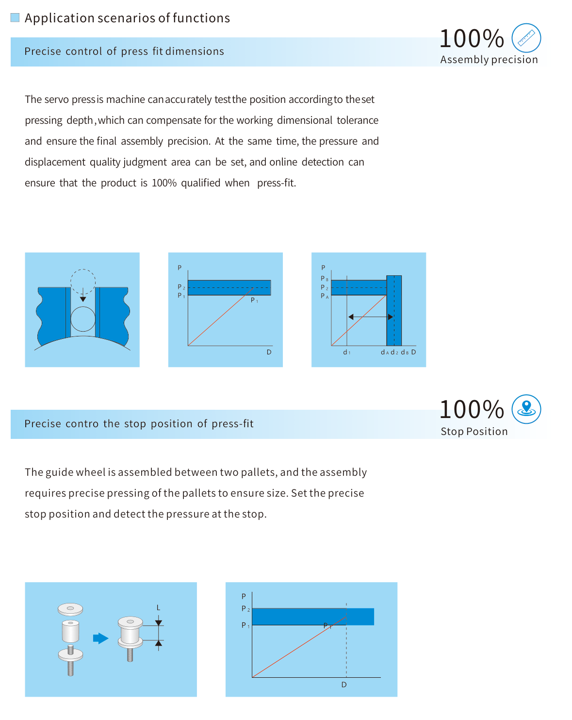
The dimension-control example uses configured pressing depth, dimensional compensation and a pressure/displacement judgment area to evaluate a press-fit assembly. The stop-position example shows a guide wheel assembled between two pallets: the pressing stop position and pressure at the stop are set for that operation.
Source illustration
Time, pressure and stop-force examples
2024 actuator catalogue, p. 81
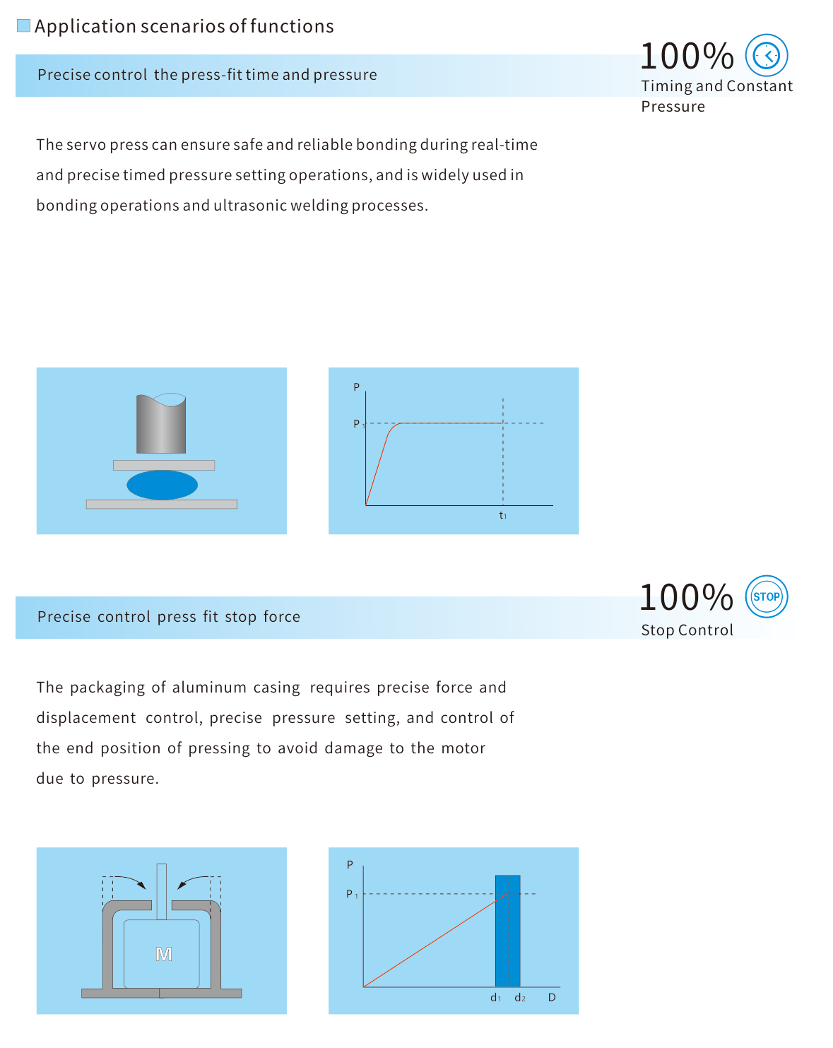
The timing/pressure example describes controlled time and pressure during bonding and ultrasonic-welding operations. The stopping-force example describes aluminium-casing packaging with force, displacement, pressure and end-position control to avoid pressure-related damage.
Source illustration