
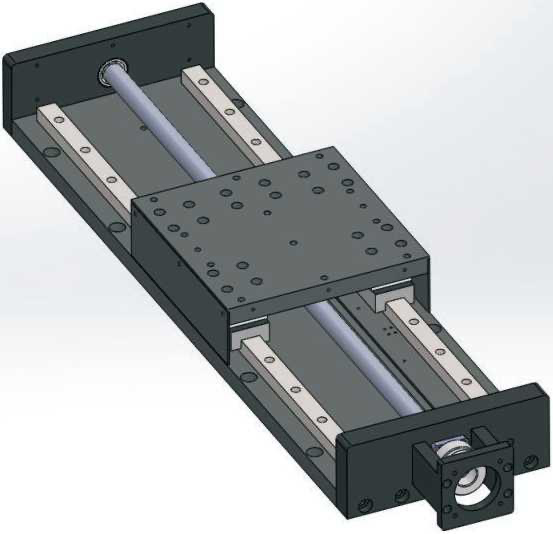
Moduli lineari · HTML Tavola di lavoro per carichi elevati
TML320HTML320 Tavola di lavoro per carichi elevati
TML320 appartiene a HTML Tavola di lavoro per carichi elevati nel catalogo Moduli lineari.
TML320 · Moduli e tavole lineari
Definire corsa utile, carico mobile, orientamento e requisiti di posizionamento. Confrontare azionamento e montaggio prima della scelta.
Confronta TML320
Per TML320, confronta questi dati: Diametro esterno della vite: 32 mm;Intervallo di corsa: 10-1200 mm. Usare dimensioni e dati del modello esatto. Confrontare carico, velocità e posizionamento con le rispettive condizioni.
Parametri e ambiti di applicazione
| Momento a sbalzo ammissibile MP Modello tecnico attuale | 810 Nm |
|---|---|
| Momento a sbalzo ammissibile MR Modello tecnico attuale | 520 Nm |
| Momento a sbalzo ammissibile MY Modello tecnico attuale | 810 Nm |
| Carico orizzontale = · 10 · 10 · Modello tecnico attuale | 250 kg |
| Carico orizzontale = · 5 · 5 · Modello tecnico attuale | 350 kg |
| Carico orizzontale = · 32 · 32 · Modello tecnico attuale | 150 kg |
| Carico verticale = · 5 · 5 · Modello tecnico attuale | 200 kg |
| Carico verticale = · 10 · 10 · Modello tecnico attuale | 180 kg |
| Carico verticale = · 32 · 32 · Modello tecnico attuale | 100 kg |
| Velocità massima = · 32 · 32 · Modello tecnico attuale | 1600 |
| Velocità massima = · 5 · 5 · Modello tecnico attuale | 250 |
| Velocità massima = · 10 · 10 · Modello tecnico attuale | 500 |
| Potenza del motore Modello tecnico attuale | 1000 W |
| Diametro esterno della vite Modello tecnico attuale | 32 mm |
| Corsa Modello tecnico attuale | 10-1200 mm |
| Application reference 1000 | The source describes steel workbenches for general or clean-room equipment, including CNC, machine-tool and transfer equipment. |
| Motor installation reference 1000 | BD:direct installation; BL:outside,left; BR:outside,right; BM:outside,lower. |
| Operating condition 1000 | Stroke over600mm may cause resonance; maximum operating speed requires source-table confirmation. No motorRPM condition is printed in this main table. |
| Ordering example (reference) 1000 | TML320-L10-S200-BD-P750W-B |
| Allowable overhang reference 1000 | The three orientation tables are allowable overhang distances in mm, not speed ratings. Lead50/25 reference rows are distinct from the main lead list on models whose main table does not print those leads. |
| Repeatability (as printed) 1000 | ±0.02/0.01 mm |
| Main table lead reference 1000 | 5/10/32 mm |
| Source power difference 1000 | Main table1000W vs ordering exampleP750W. |
Allowable overhang distances · horizontal · original p.94
| Printed lead/load | A(mm) | B(mm) | C(mm) |
|---|---|---|---|
| Lead50 · 5kg | 1940 mm | 1285 mm | 1264 mm |
| Lead50 · 10kg | 1490 mm | 1125 mm | 1120 mm |
| Lead50 · 15kg | 1210 mm | 1045 mm | 1048 mm |
| Lead25 · 5kg | 1938 mm | 1283 mm | 1260 mm |
| Lead25 · 10kg | 1488 mm | 1122 mm | 1117 mm |
| Lead25 · 22kg | 1235 mm | 1041 mm | 1045 mm |
| Lead10 · 15kg | 1392 mm | 1076 mm | 1079 mm |
| Lead10 · 25kg | 1182 mm | 1020 mm | 1025 mm |
| Lead10 · 30kg | 1111 mm | 956 mm | 750 mm |
| Lead05 · 30kg | 1111 mm | 956 mm | 750 mm |
| Lead05 · 50kg | 565 mm | 560 mm | 530 mm |
| Lead05 · - | - mm | - mm | - mm |
A/B/C distance directions correspond to the original installation diagrams, not0°/45°/90° and not speed. All source rows including dash row are retained.
The distance source printsLead50/Lead25 while this model main table lists other lead values; no lead mapping is inferred.
Allowable overhang distances · wall · original p.94
| Printed lead/load | A(mm) | B(mm) | C(mm) |
|---|---|---|---|
| Lead50 · 5kg | 1940 mm | 1285 mm | 1264 mm |
| Lead50 · 10kg | 1490 mm | 1125 mm | 1120 mm |
| Lead50 · 15kg | 1210 mm | 1045 mm | 1048 mm |
| Lead25 · 5kg | 1938 mm | 1283 mm | 1260 mm |
| Lead25 · 10kg | 1488 mm | 1122 mm | 1117 mm |
| Lead25 · 22kg | 1235 mm | 1041 mm | 1045 mm |
| Lead10 · 15kg | 1392 mm | 1076 mm | 1079 mm |
| Lead10 · 25kg | 1182 mm | 1020 mm | 1025 mm |
| Lead10 · 30kg | 1111 mm | 956 mm | 750 mm |
| Lead05 · 30kg | 1111 mm | 956 mm | 750 mm |
| Lead05 · 50kg | 565 mm | 560 mm | 530 mm |
| Lead05 · - | - mm | - mm | - mm |
A/B/C distance directions correspond to the original installation diagrams, not0°/45°/90° and not speed. All source rows including dash row are retained.
The distance source printsLead50/Lead25 while this model main table lists other lead values; no lead mapping is inferred.
Allowable overhang distances · vertical · original p.94
| Printed lead/load | A(mm) | B(mm) | C(mm) |
|---|---|---|---|
| Lead50 · 5kg | 1940 mm | 1285 mm | 1264 mm |
| Lead50 · 10kg | 1490 mm | 1125 mm | 1120 mm |
| Lead50 · 15kg | 1210 mm | 1045 mm | 1048 mm |
| Lead25 · 5kg | 1938 mm | 1283 mm | 1260 mm |
| Lead25 · 10kg | 1488 mm | 1122 mm | 1117 mm |
| Lead25 · 22kg | 1235 mm | 1041 mm | 1045 mm |
| Lead10 · 15kg | 1392 mm | 1076 mm | 1079 mm |
| Lead10 · 25kg | 1182 mm | 1020 mm | 1025 mm |
| Lead10 · 30kg | 1111 mm | 956 mm | 750 mm |
| Lead05 · 30kg | 1111 mm | 956 mm | 750 mm |
| Lead05 · 50kg | 565 mm | 560 mm | 530 mm |
| Lead05 · - | - mm | - mm | - mm |
A/B/C distance directions correspond to the original installation diagrams, not0°/45°/90° and not speed. All source rows including dash row are retained.
The distance source printsLead50/Lead25 while this model main table lists other lead values; no lead mapping is inferred.
Parla con HTROBOT
- Emailemmy@htrobot.com
- Telefono+86 152 0225 5004
- Negozio AlibabaVisita il nostro negozio Alibaba