
Solution
Custom gantry systems
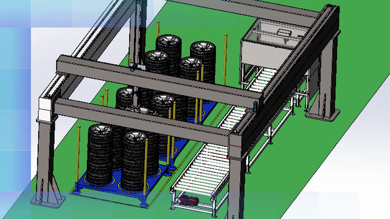
Gantry structures can be assembled from ball-screw linear stages. The required function, travel, speed and load guide the choice of stages.
What to confirm for this system
Name the part, its orientation, pick and place points or process stations, and the motion required between them. A Cartesian arrangement uses separate linear axes; the actual number and layout follow the task. Include the tool or gripper and how it contacts the workpiece.
Provide the floor or machine envelope, mounting surfaces, obstacles, power and control interface, and operating environment. For handling, show the loading and unloading stations and the end tool. A simple layout sketch makes these interfaces easier to review.
Ask about this page
Useful details to include:
- Function of the equipment
- Travel per axis (mm)
- Payload (kg) and speed
- Operating environment
Saved in this browser only. Nothing is sent.