
Technical article
Plan a Cartesian gantry: project checklist
Plan the workpiece path, each axis and the installation before discussing a gantry layout.
From a motion task to a gantry layout
A Cartesian system combines linear axes. Start with the workpiece path and process stations, then decide whether height motion is needed. The system examples show different frames and drive arrangements, so use the example closest to the task as a discussion reference.
Review axes and interfaces together
State the carried part and tool mass, travel and positioning needs for each axis. Add the mounting envelope, power and control interfaces. Ask for the proposed layout and its own technical values rather than combining values from several examples.
Continue comparing
1. Describe the work before choosing axes
Name the part, its orientation, pick and place points or process stations, and the motion required between them. A Cartesian arrangement uses separate linear axes; the actual number and layout follow the task. Include the tool or gripper and how it contacts the workpiece.
2. Record requirements for each axis
For X, Y and any Z axis, give usable travel, load, target speed or cycle time, and positioning needs. Include the workpiece and tool mass separately. Different examples use screw, belt or rack drives, so compare the proposed axis against your task.
3. Define interfaces and operating conditions
Provide the floor or machine envelope, mounting surfaces, obstacles, power and control interface, and operating environment. For handling, show the loading and unloading stations and the end tool. A simple layout sketch makes these interfaces easier to review.
4. Send a reviewable project brief
Send a sketch if available and list the function, travel on each axis, payload, speed, environment and fixed constraints. Open the related gantry examples to discuss the frame and tooling, then request a drawing and technical values for the proposed configuration.
Catalogue engineering references
Modman application and combination references
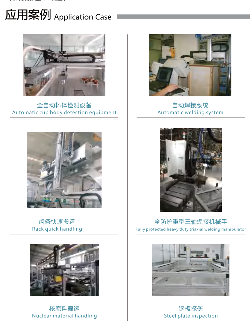
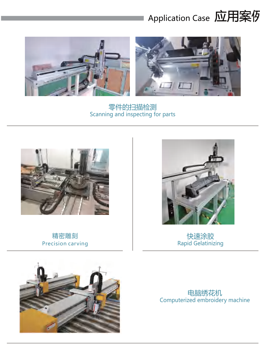
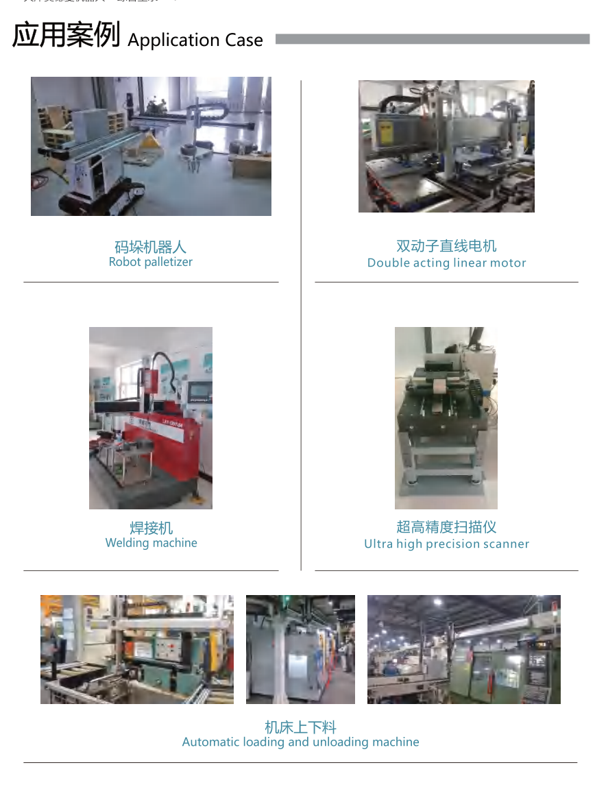
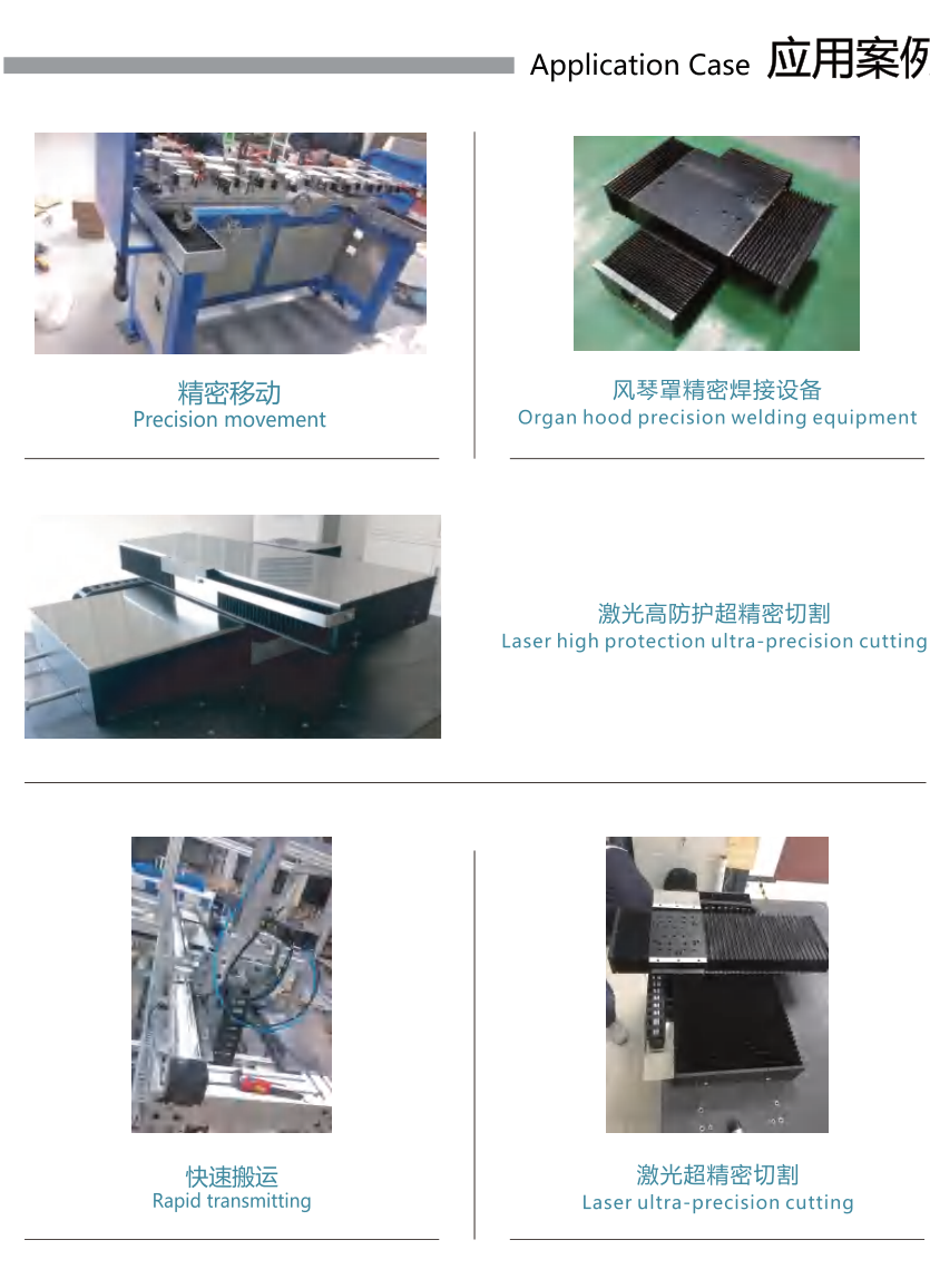
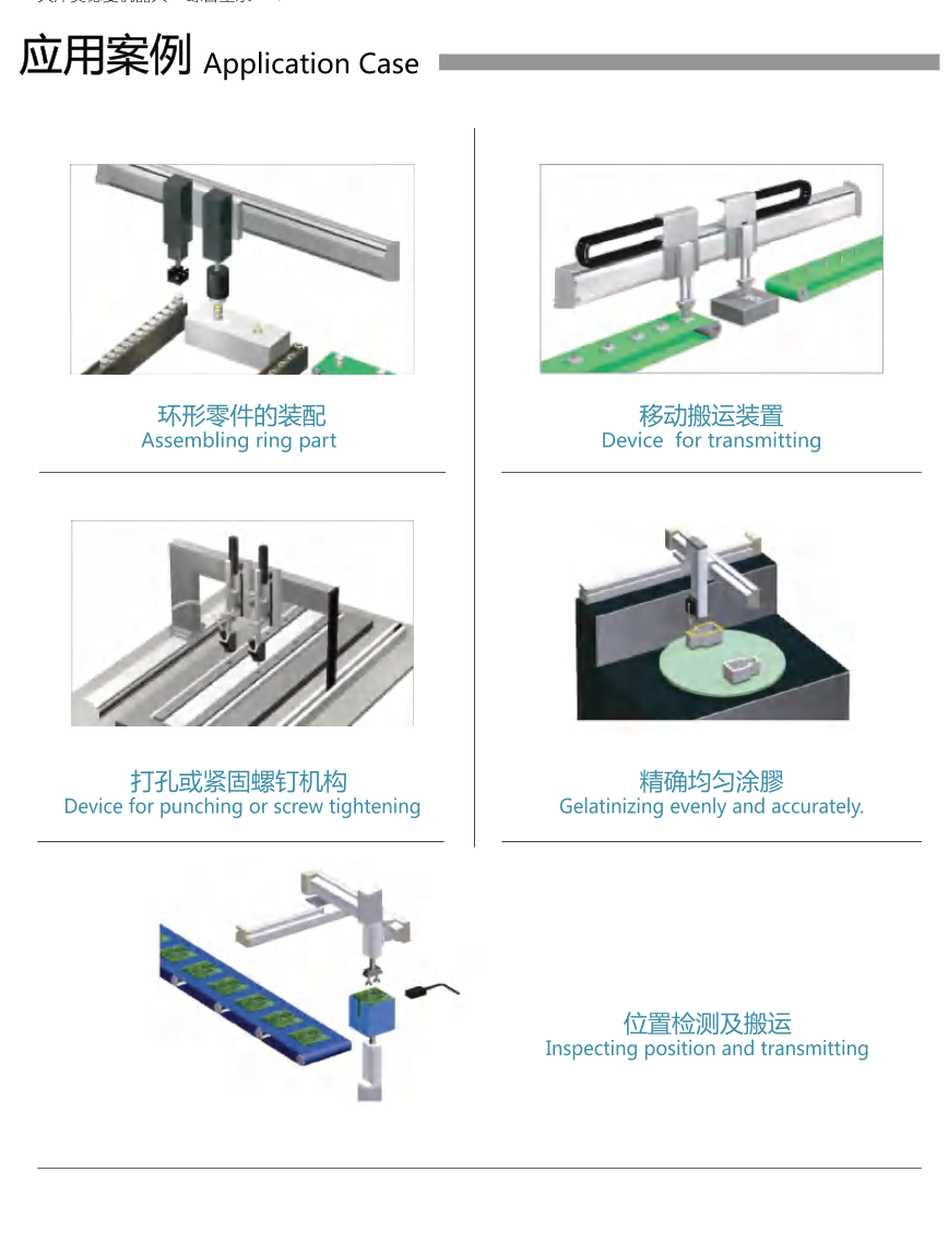
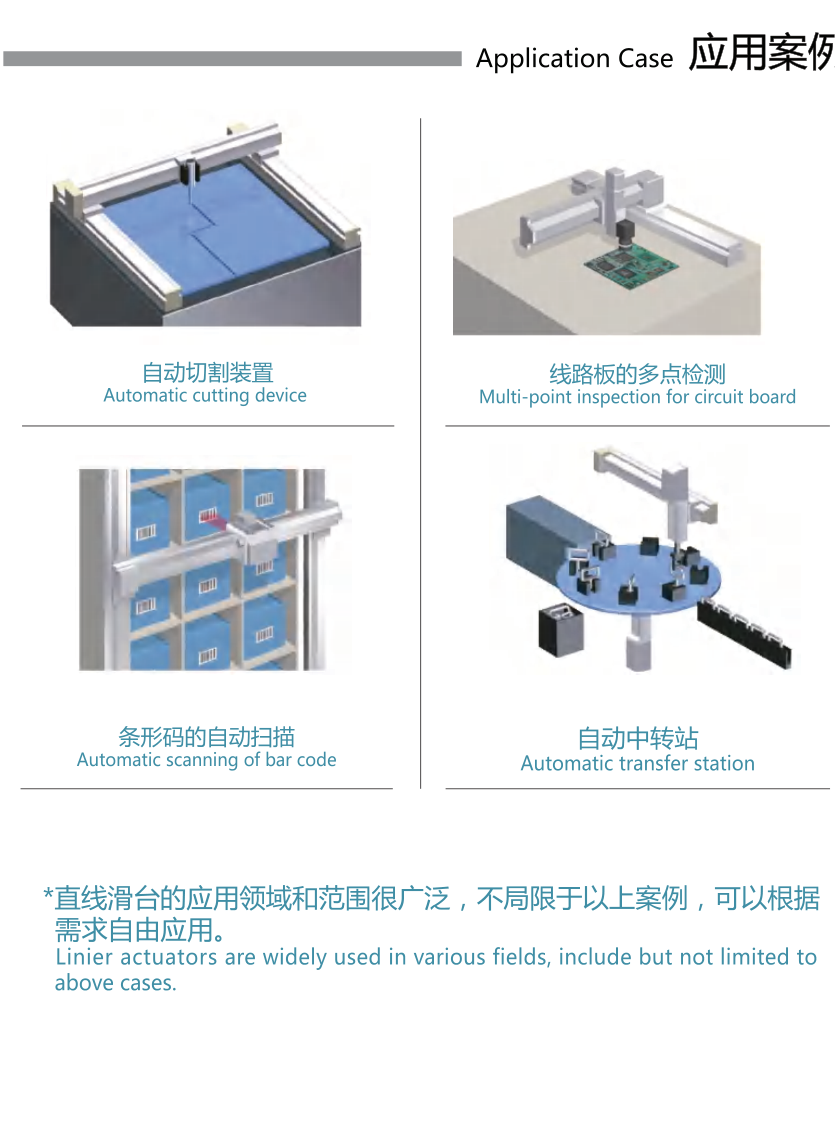
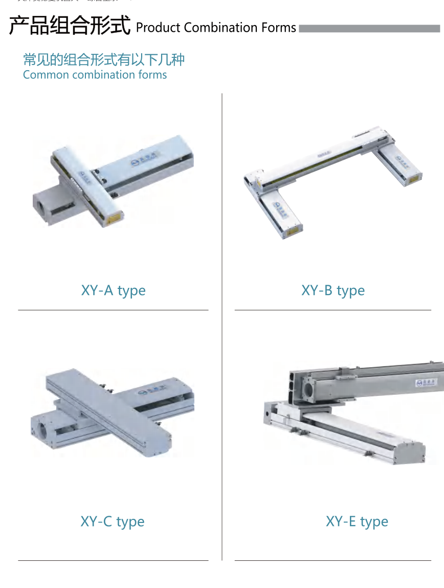
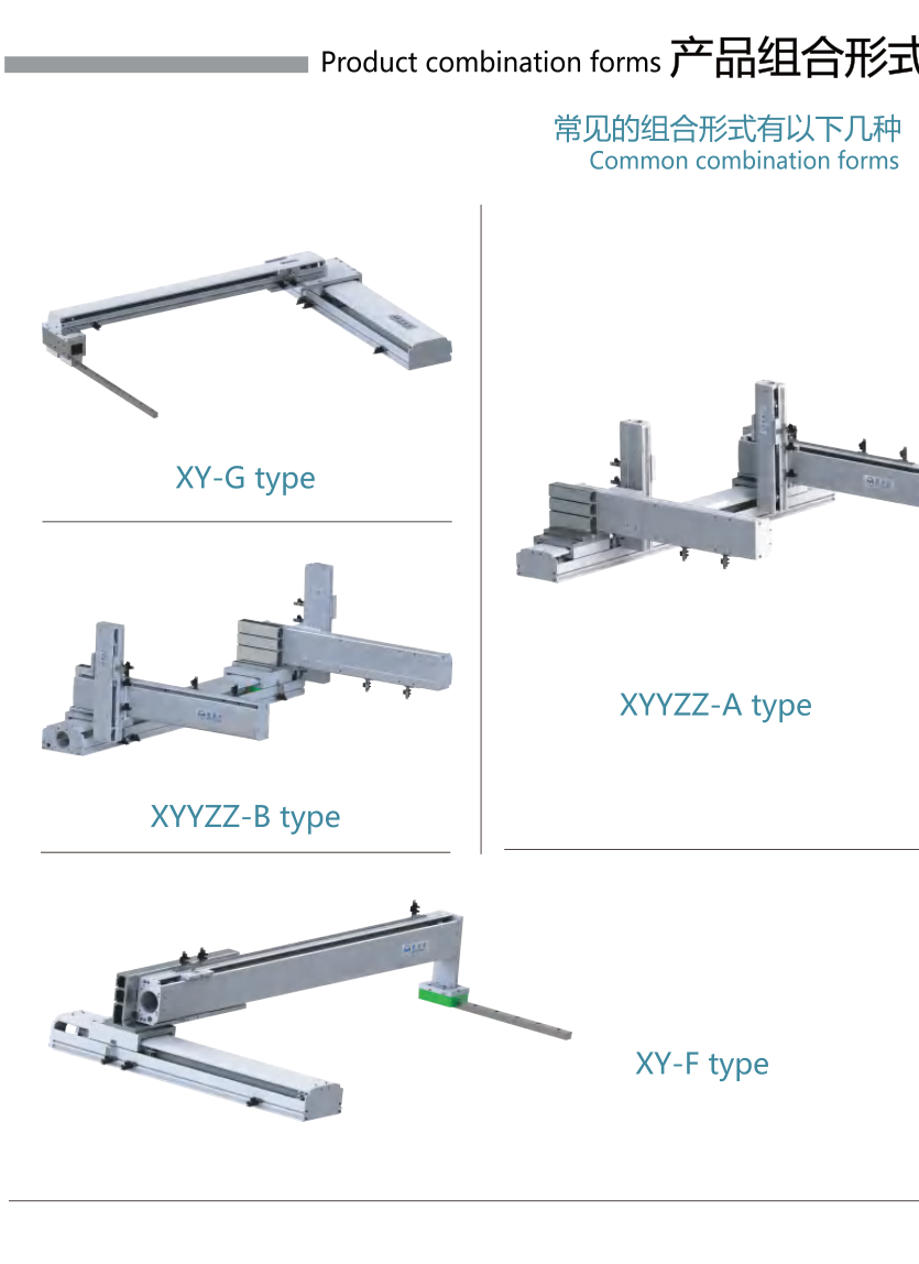
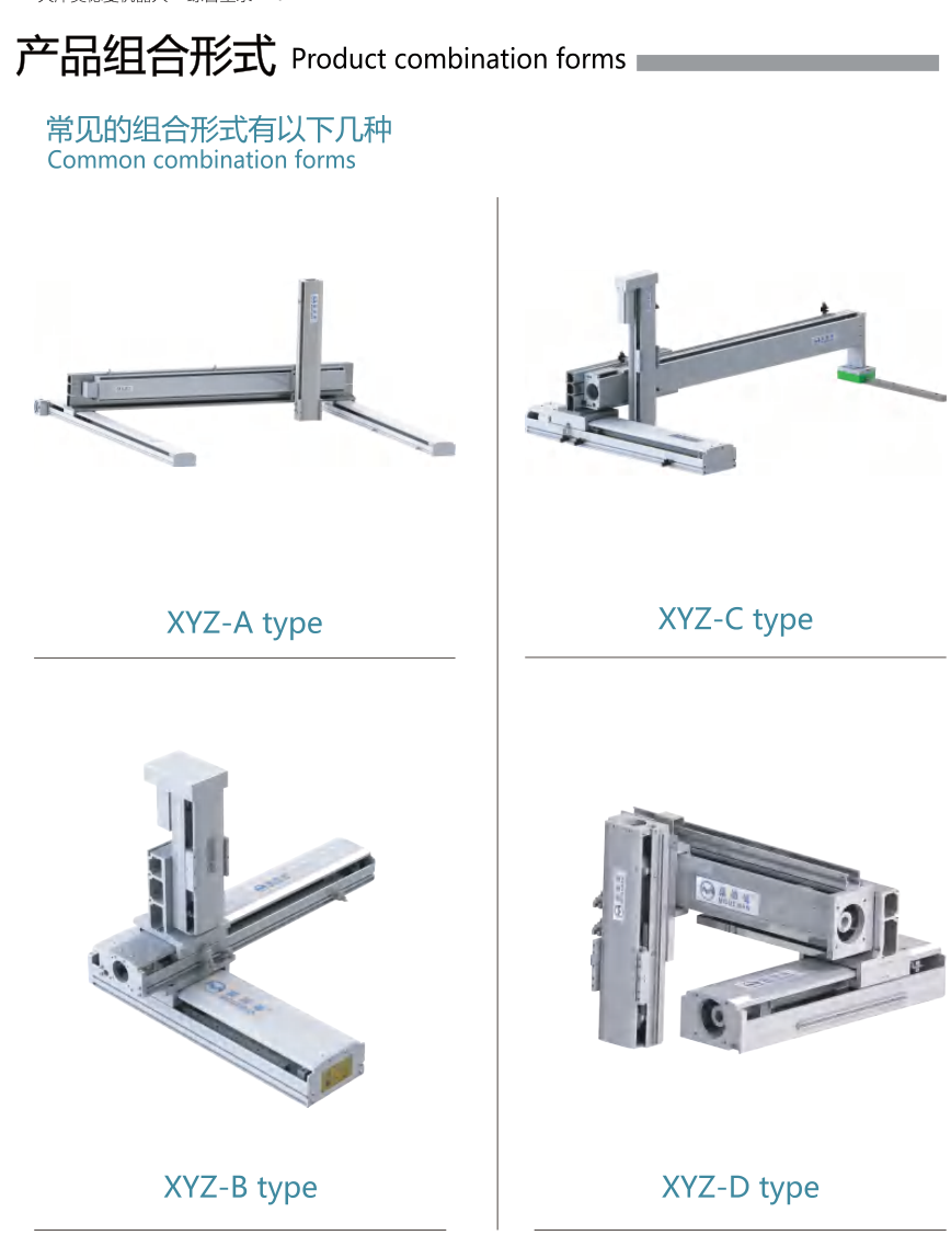
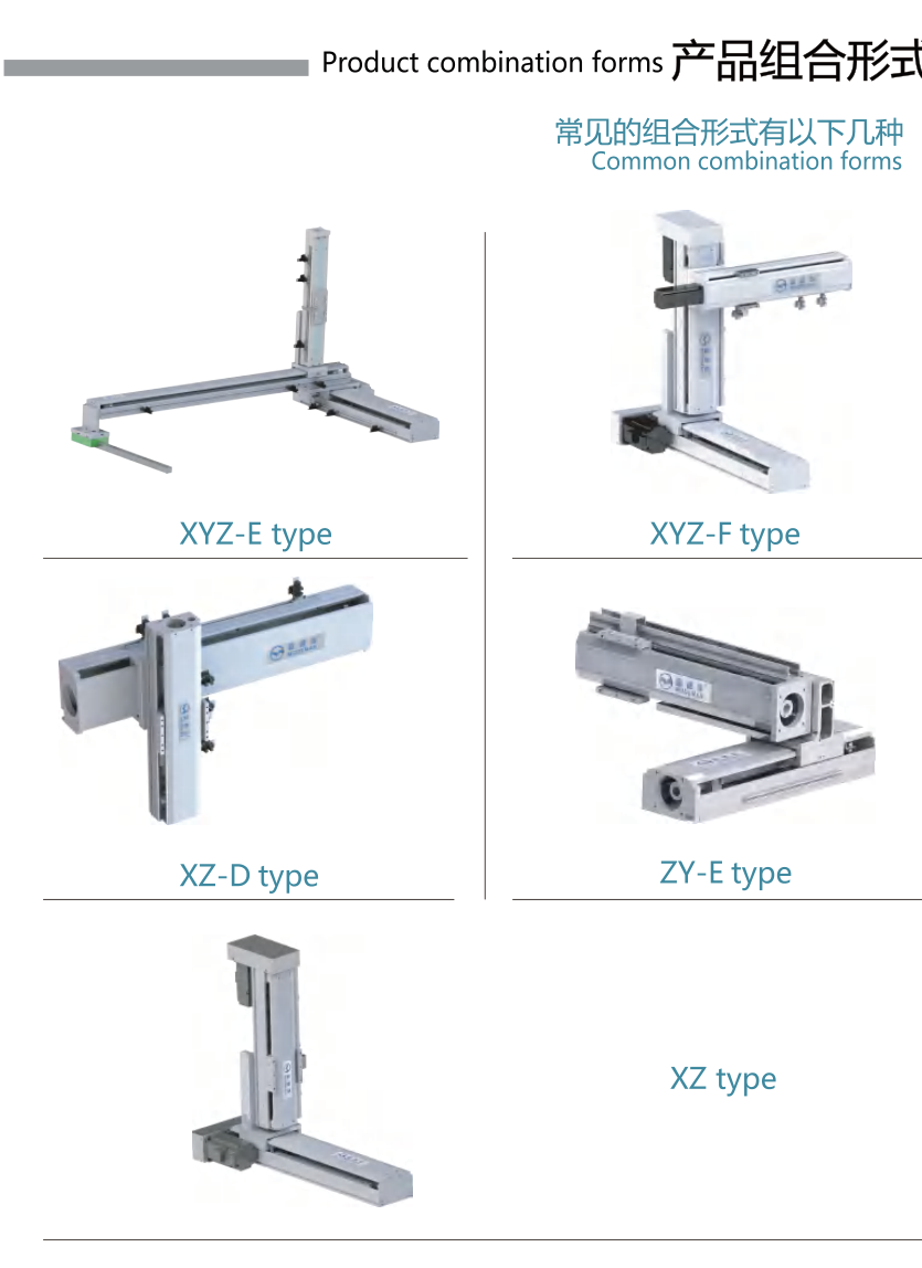
Original Modman application examples: cup-body inspection, welding, rack handling, protected heavy three-axis handling, nuclear-material handling, steel-plate inspection, scanning, precision carving, dispensing, embroidery, palletizing, double-moving linear motors, precision movement, organ-cover welding, laser cutting, loading/unloading, assembly, transmission, screw tightening, inspection and transfer stations. These are original supplier examples, not HTROBOT project claims. Combination names are XY-A/B/C/E/F/G; XYYZZ-A/B; XYZ-A/B/C/D/E/F; XZ-D, ZY-E and XZ. Layout names describe illustrated arrangements; they do not establish a saleable configuration or compatibility.
TKA assembly and accessory references
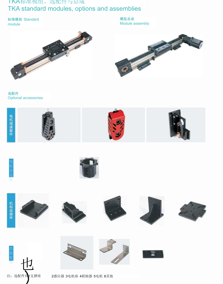
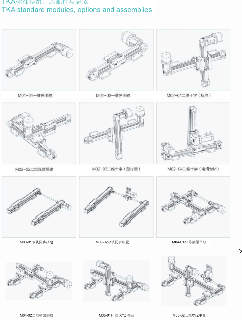
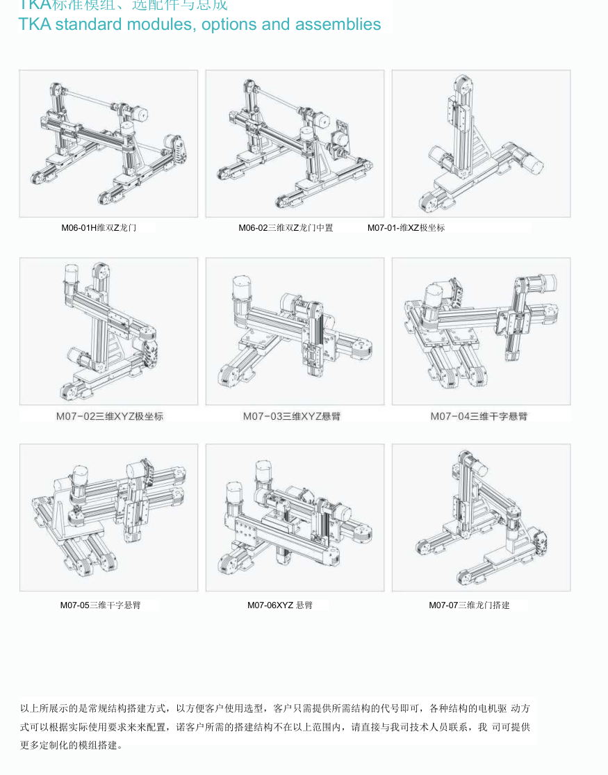
Original TKA standard modules, options and assemblies: motor mounting accessories, couplings, module connection plates/brackets and fixing accessories. Annotated note: flange/bracket choices and motor/reducer interfaces require the original installation drawings. Original assembly labels M01-01/02, M02-01/02/03/04, M03-01/02, M04-01/02, M05-01/02, M06-01/02 and M07-01/02/03/04/05/06/07 are layout references for single axes, crosses, parallel axes, XY, gantry and XYZ arrangements. They are not new SKUs and do not transfer load ratings among axes. The native figures preserve the exact assembly labels.
Tuogu DH customized handling and accessories
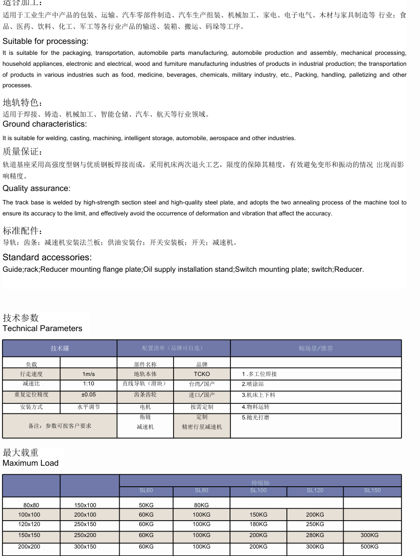
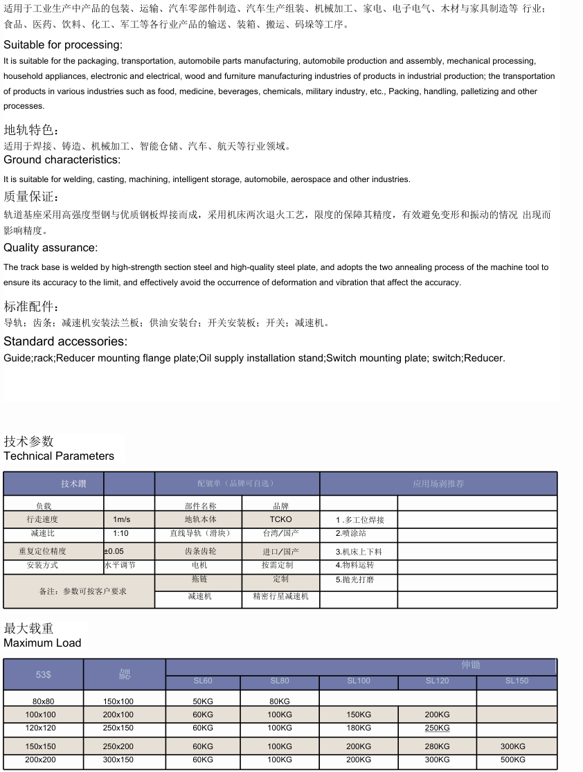
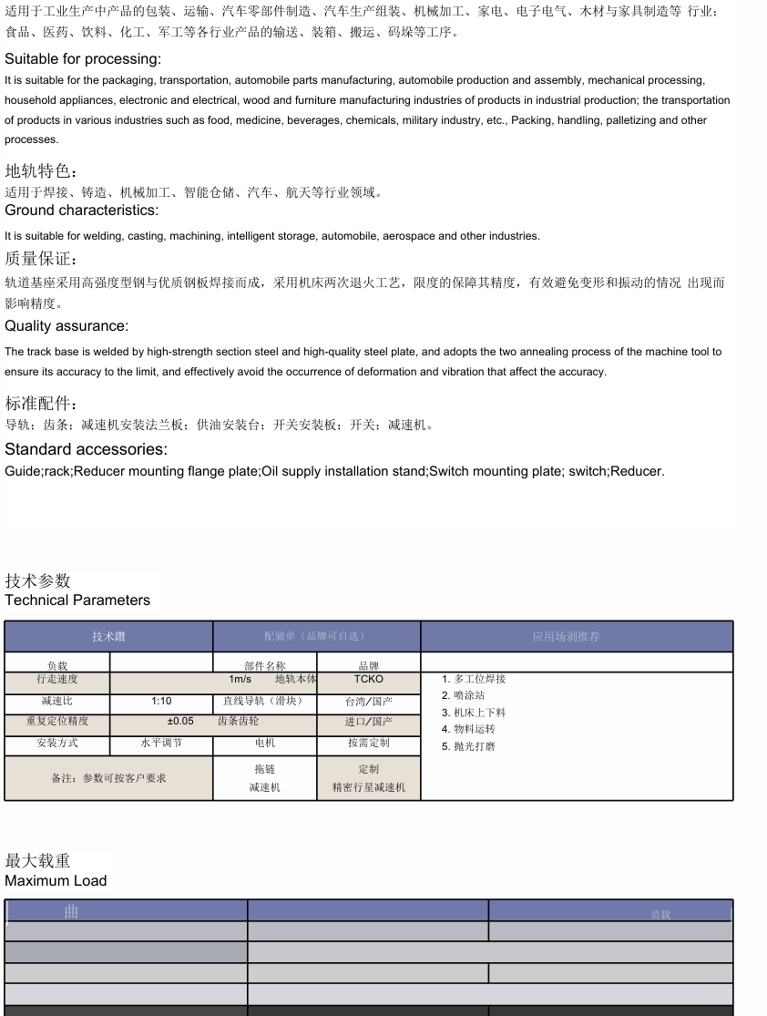
Original DH systems are project references. Shared text states speed1m/s, reducer ratio1:10 and repeatability±0.05 (no unit printed in that overview). Do not treat those shared examples as an existing product rating. Horizontal installation adjustment, guide/rack positioning, flange/coupling mounting, oil switches and reducers require their own original instructions. Original frame/load comparison below is kg; blanks are source blanks. SL120 is a source reference column, not a newly created catalogue model. Frame sections | SL60 | SL80 | SL100 | SL120 | SL150 80×80 / 150×100 | 50 | 80 | | | 100×100 / 200×100 | 60 | 100 | 150 | 200 | 120×120 / 250×150 | 60 | 100 | 180 | 250 | 150×150 / 250×200 | 60 | 100 | 200 | 280 | 300 200×200 / 300×150 | 60 | 100 | 200 | 300 | 500
Tuogu safety and maintenance references
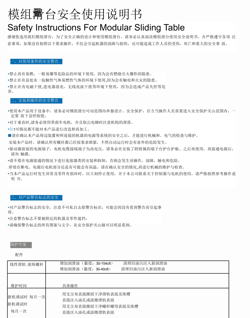
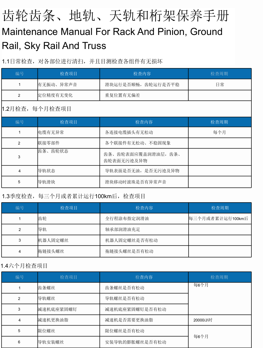
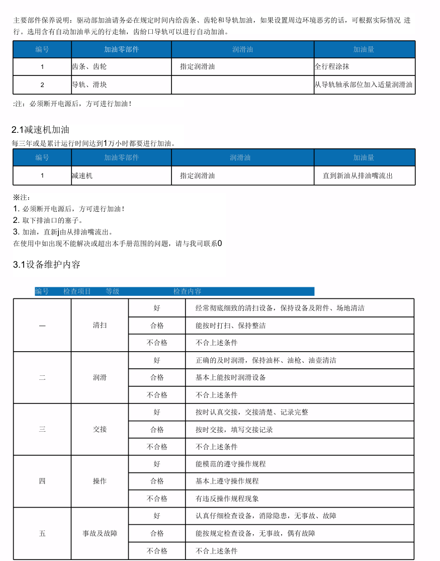
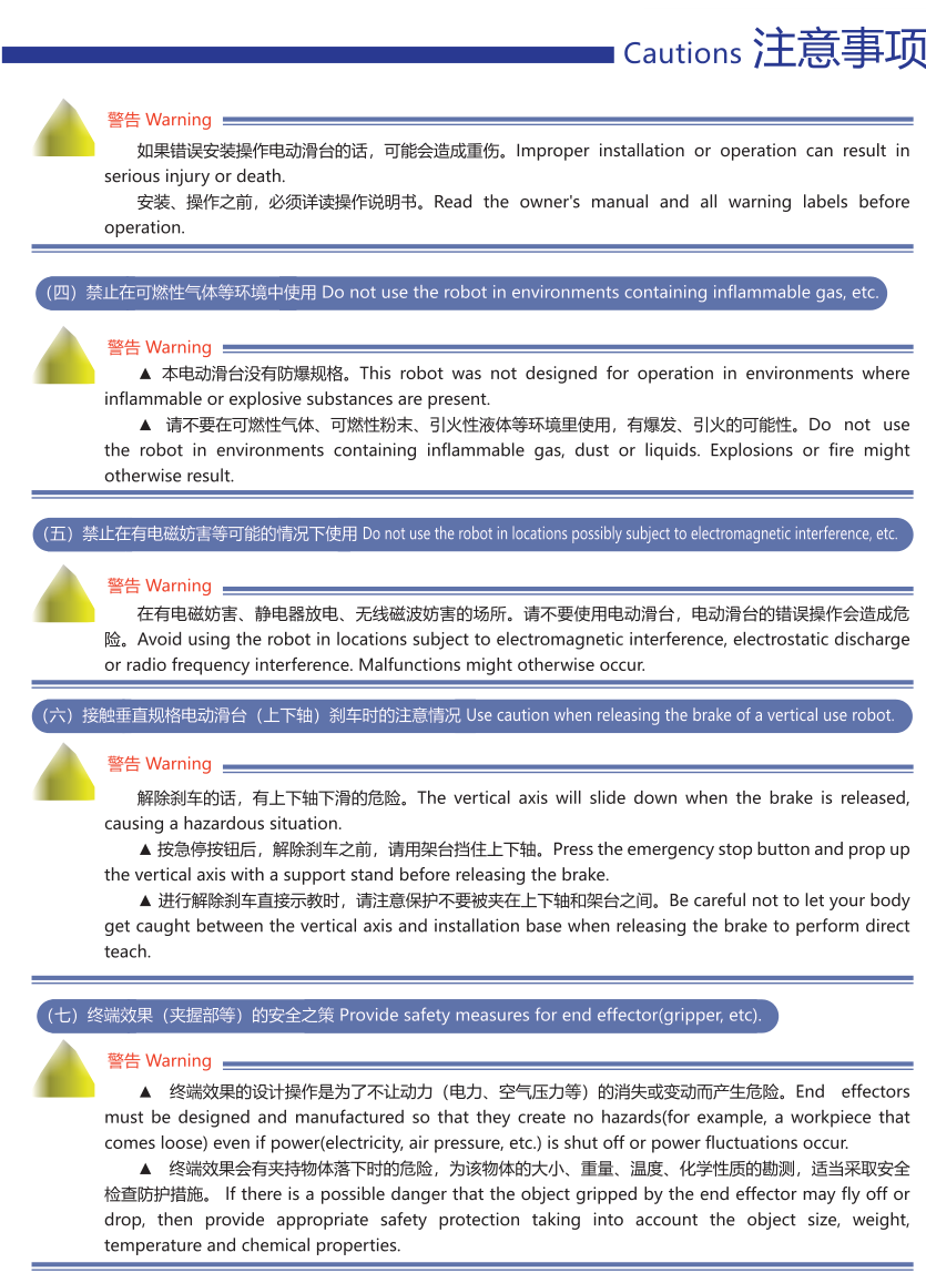
Original module safety: avoid combustible/explosive, water/corrosive-gas and electromagnetic-interference environments; guard the motion envelope, use emergency stop before entering it, use braking/support for vertical axes, isolate power before connecting or maintenance, check mounting fasteners and protect high-voltage terminals. Do not modify the module or remove warning labels. Rail/screw lubrication is required at commissioning and monthly; source viscosity strings are damaged and are not a verified oil specification. Original rack/truss schedule: daily cleanliness, motion/noise and repeat position; monthly cables, connecting parts, rack/gears, guides and slider sound; quarterly or100km gear/guide lubrication, robot mounting and chain fasteners; six-month rack/guide/base/limit/anchor fasteners. Reducer replacement-grease row states20000h, while the subsequent reducer refill instruction says three years or10000h. Both source schedules remain separate; no unified interval is invented. Isolate power before lubrication. Source grading covers cleaning, lubrication, shift handover, operation, accidents/faults.
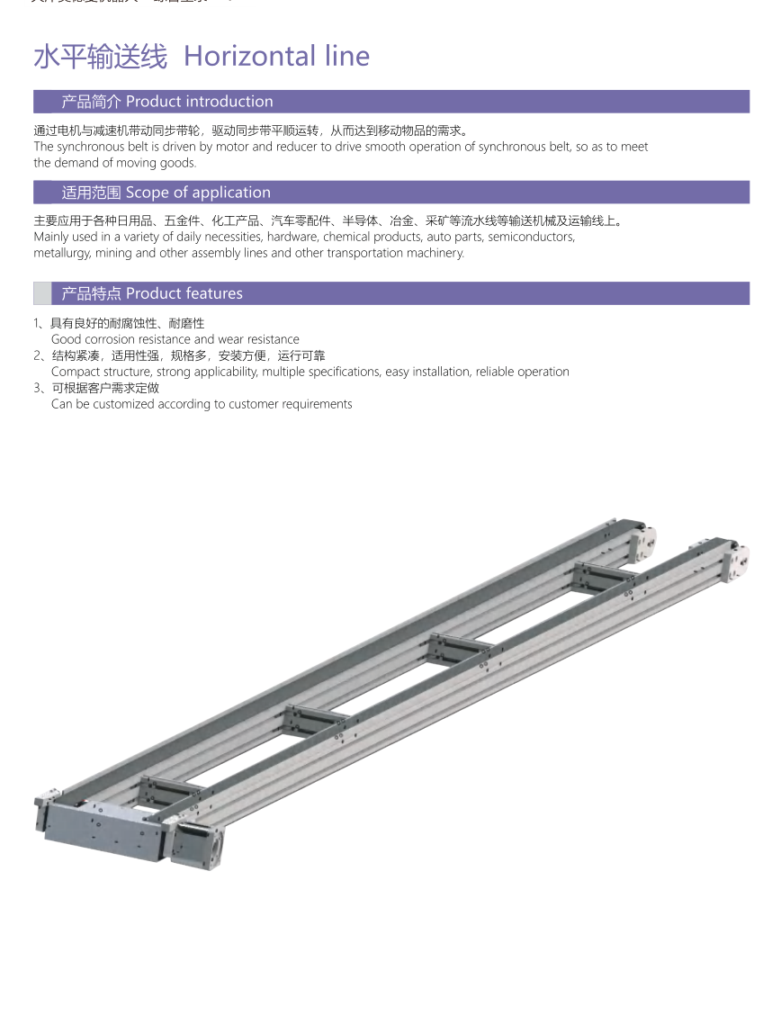
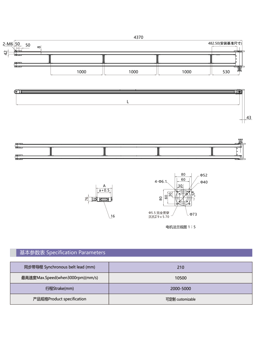
Horizontal conveyor
Motor/reducer-driven synchronous belt, conveying examples; dimensions are example-specific. Synchronous belt lead | 210mm Maximum speed at3000rpm | 10500mm/s Stroke | 2000–5000mm Specification | customizable
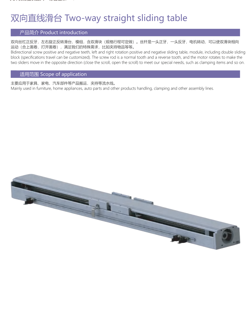
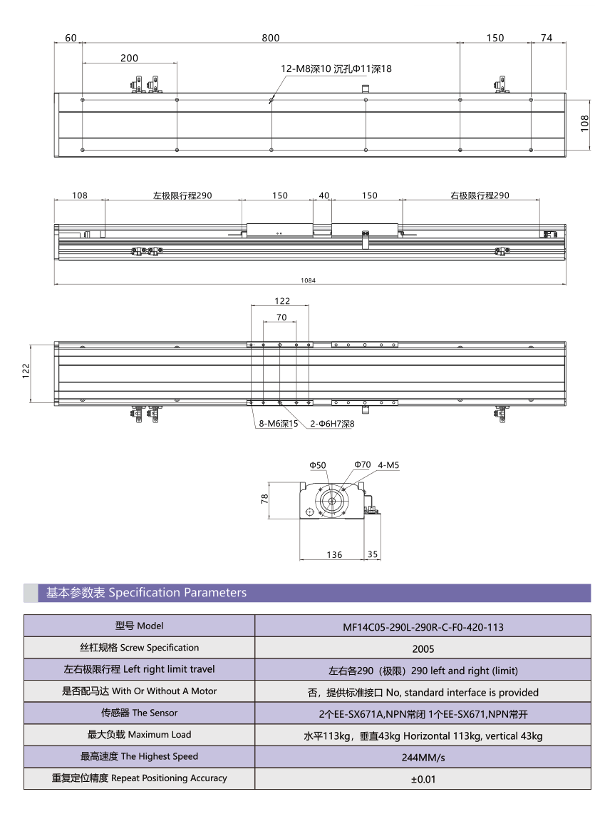
Two-way straight sliding table
A single motor drives opposite-thread screws for paired opening/closing; example only. Model | MF14C05-290L-290R-C-F0-420-113 Screw specification | 2005 Left/right limit travel | 290mm / 290mm Motor | No; standard interface provided Sensor | 2 EE-SX671A,NPN;1 EE-SX671,NPN Maximum load | horizontal113kg;vertical43kg Highest speed | 244mm/s Repeat positioning accuracy | ±0.01; unit not printed in row
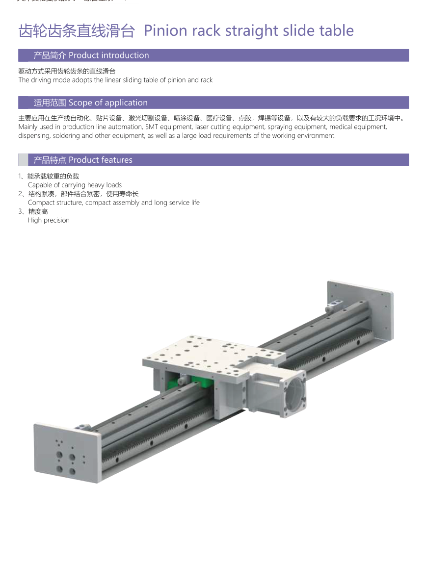
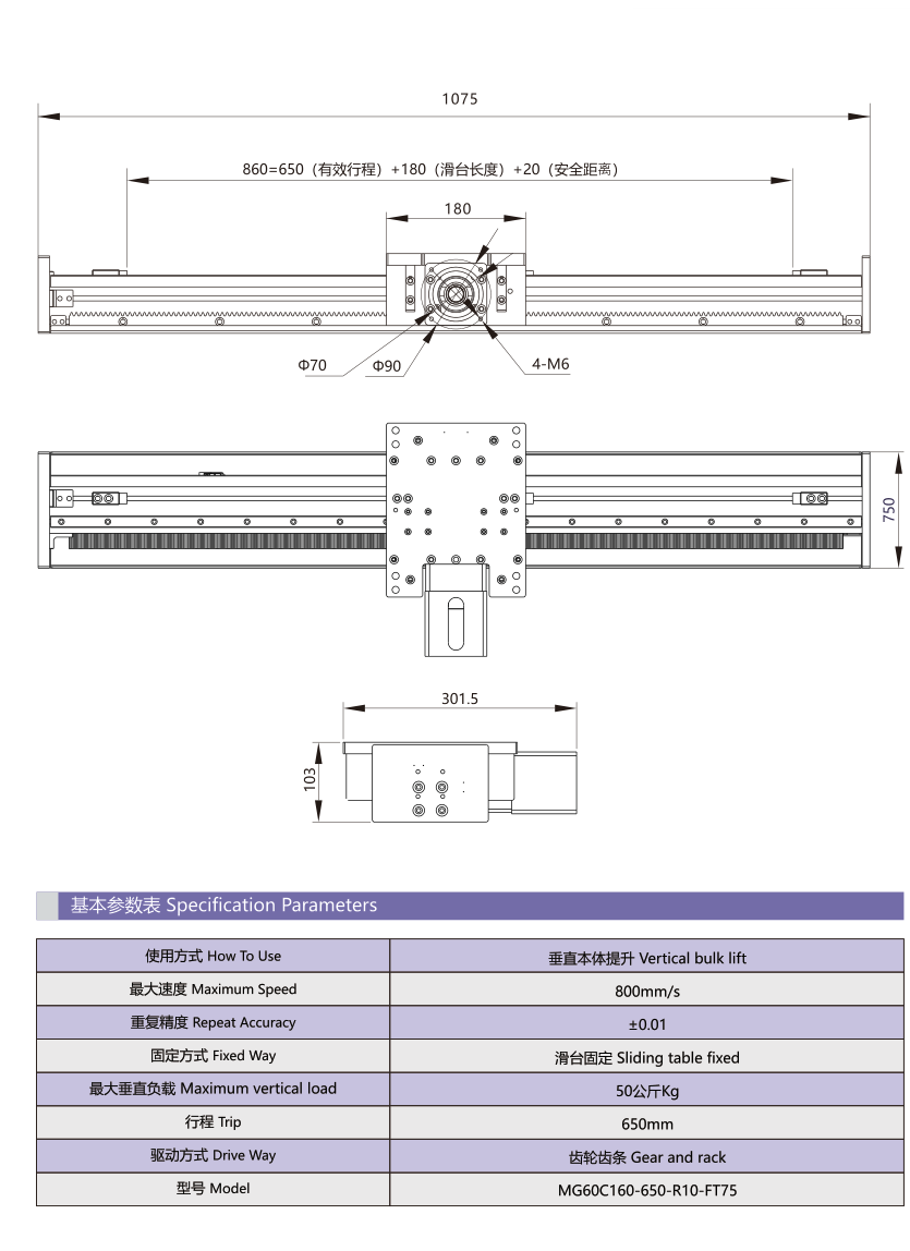
Pinion/rack straight slide
Separate heavy-load customization example. Model | MG60C160-650-R10-FT75 Use | vertical bulk lift Maximum speed | 800mm/s Repeat accuracy | ±0.01; unit not printed Fixed way | sliding table fixed Maximum vertical load | 50kg Travel | 650mm Drive | gear and rack
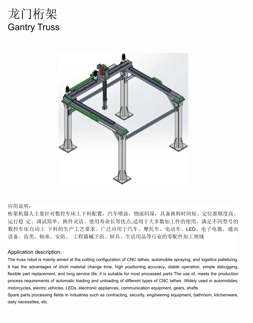
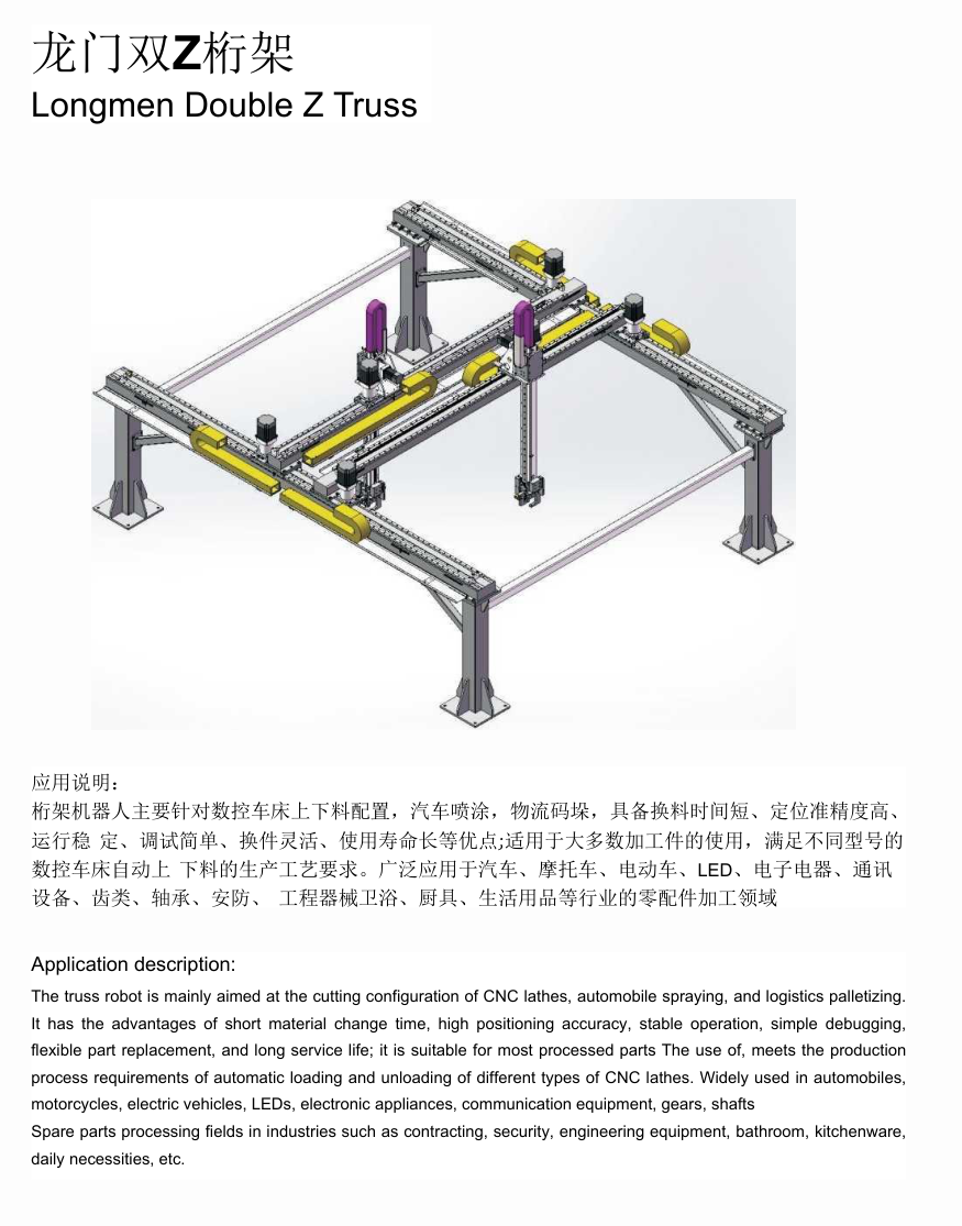
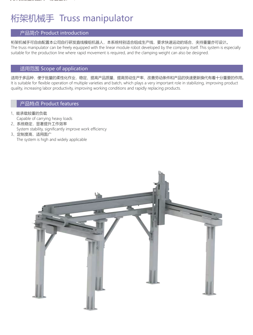
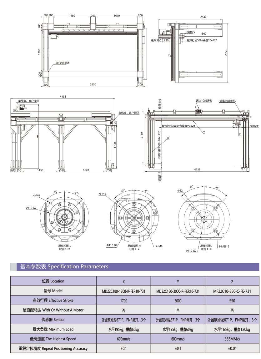
Truss manipulator
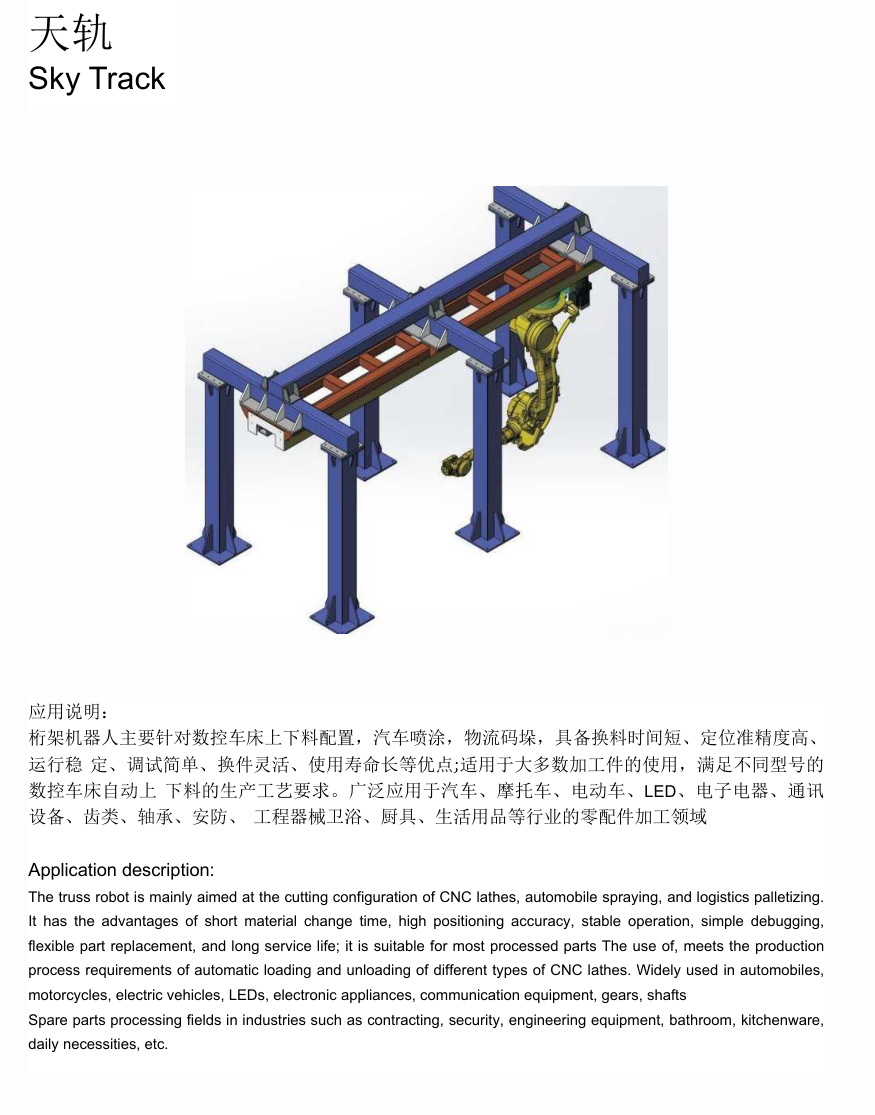
Model/sensor literal details remain in native table; examples are independent axes, no synthetic combination rating. Axis | X | Y | Z Effective stroke(mm) | 1700 | 3000 | 550 Model | MD22C180-1700-R-FER10-731 | MD22C180-3000-R-FER10-731 | MF22C10-550-C-FE-731 Motor | No | No | No Sensor | Omron671P;PNP normally-open;3 | Omron671P;PNP normally-open;3 | Omron671P;PNP normally-open;3 Maximum load(kg) | horizontal195;vertical60 | horizontal195;vertical60 | horizontal165;vertical120 Highest speed(mm/s) | 600 | 600 | 333 Repeatability | ±0.1 | ±0.1 | ±0.01
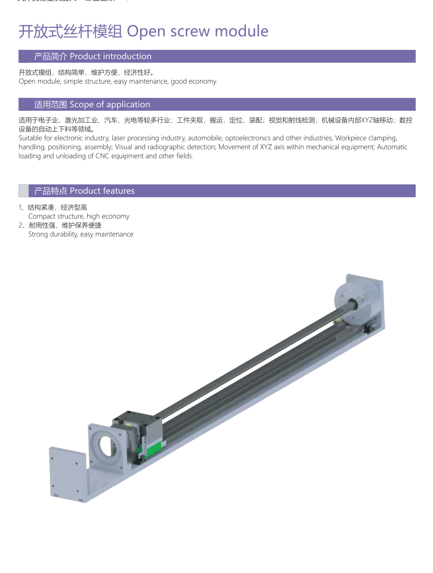
Open screw module
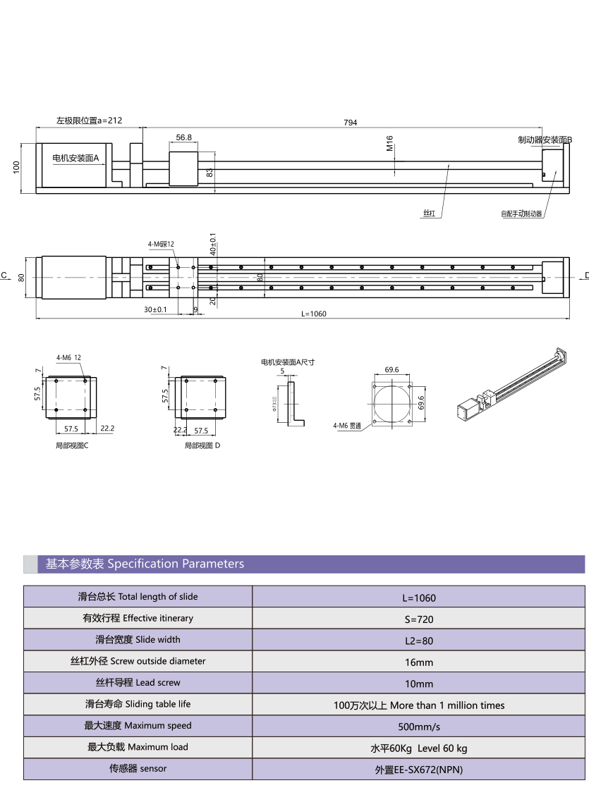
Units not printed for L/S/L2 are retained without inferred conversion. Slide length | L=1060 Effective stroke | S=720 Slide width | L2=80 Screw outer diameter | 16mm Lead | 10mm Life | more than1million times Maximum speed | 500mm/s Maximum load | horizontal60kg Sensor | EE-SX672(NPN)
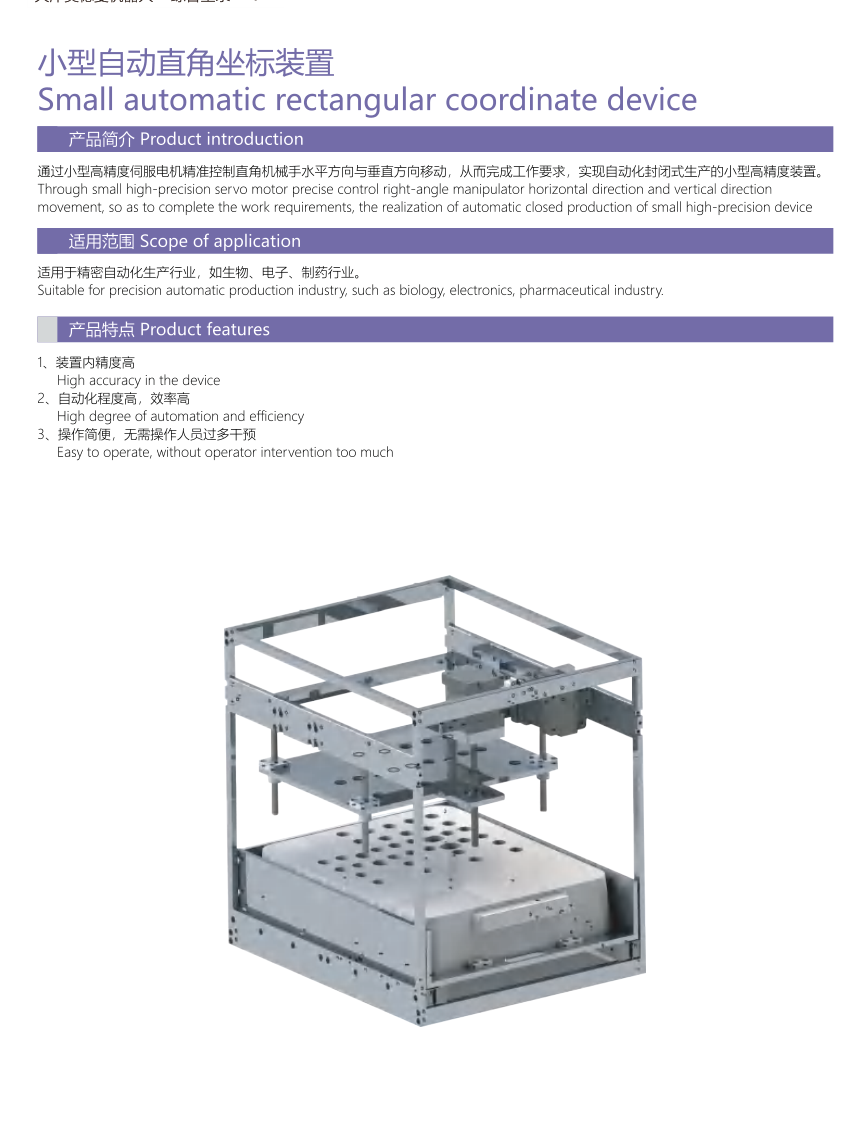
Small automatic rectangular-coordinate device
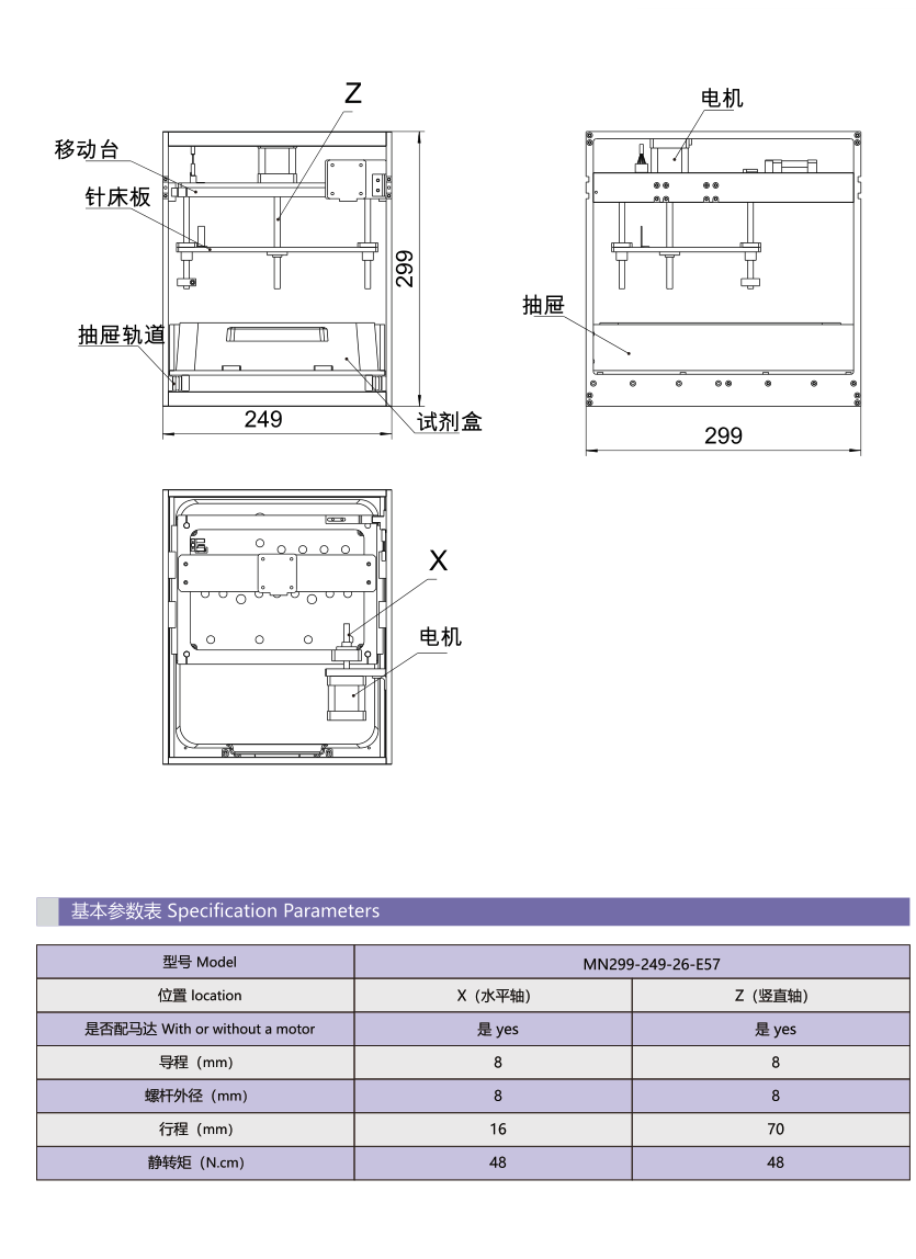
Original small-device example, not an existing product configuration. Model | MN299-249-26-E57 Axis | X(horizontal) | Z(vertical) Motor | yes | yes Lead(mm) | 8 | 8 Screw outer diameter(mm) | 8 | 8 Travel(mm) | 16 | 70 Torque(N.cm) | 48 | 48
Large linear slide
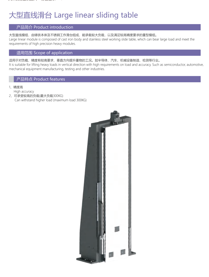
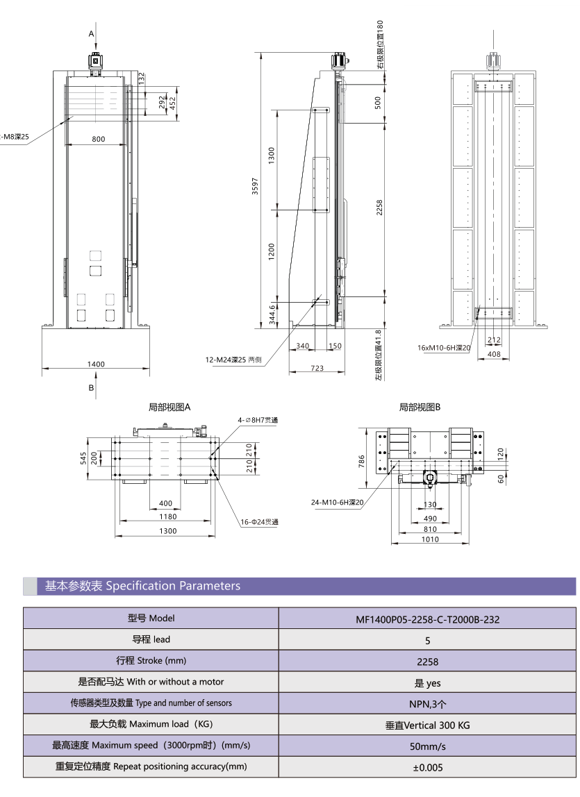
Keep source lead5 and printed speed50 separately; do not calculate250. Model | MF1400P05-2258-C-T200B-232 Lead | 5; unit not printed Stroke | 2258mm Motor | yes Sensors | NPN;3 Maximum load | vertical300kg Maximum speed at3000rpm | 50mm/s Repeatability | ±0.005mm
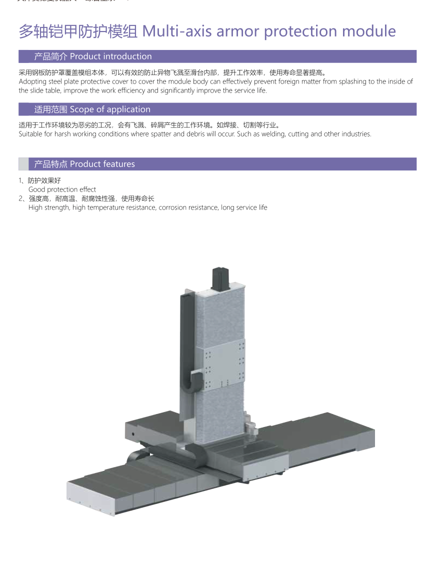
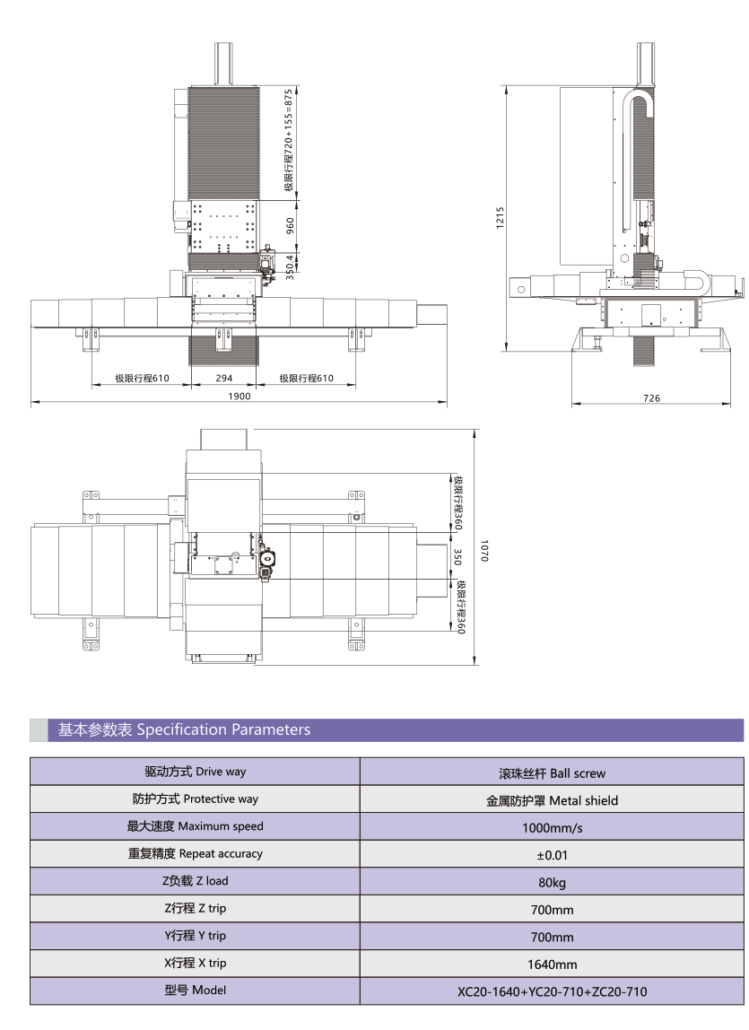
Multi-axis armour protection module
Source model710 and table travel700 both retained. Splash-protection reference is not a certified clean-room rating. Model | XC20-1640+YC20-710+ZC20-710 Drive | ball screw Protection | metal shield Maximum speed | 1000mm/s Repeat accuracy | ±0.01; no unit printed Z load | 80kg Z travel | 700mm Y travel | 700mm X travel | 1640mm
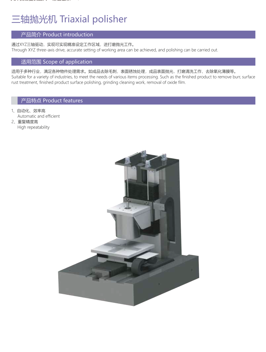
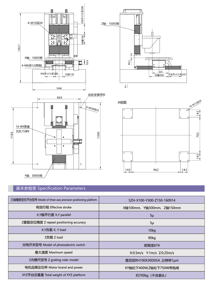
Triaxial polisher
Original example; source μ labels remain as printed. Model | SZH-X100-Y300-Z150-160914 Stroke | X100,Y300,Z150mm X/Y parallelism | 5μ Z repeatability | 5μ X/Y load | 10kg Z load | 90kg Photoelectric switch | Omron674 Max speed | X0.5,Y1,Z0.25m/s Z grating ruler | Renishaw RH100X30D05A Optical scale resolution | 1μm Motor | X/Y Panasonic400W;Z Panasonic750W with brake Total weight | approximately700kg(without grinding head)
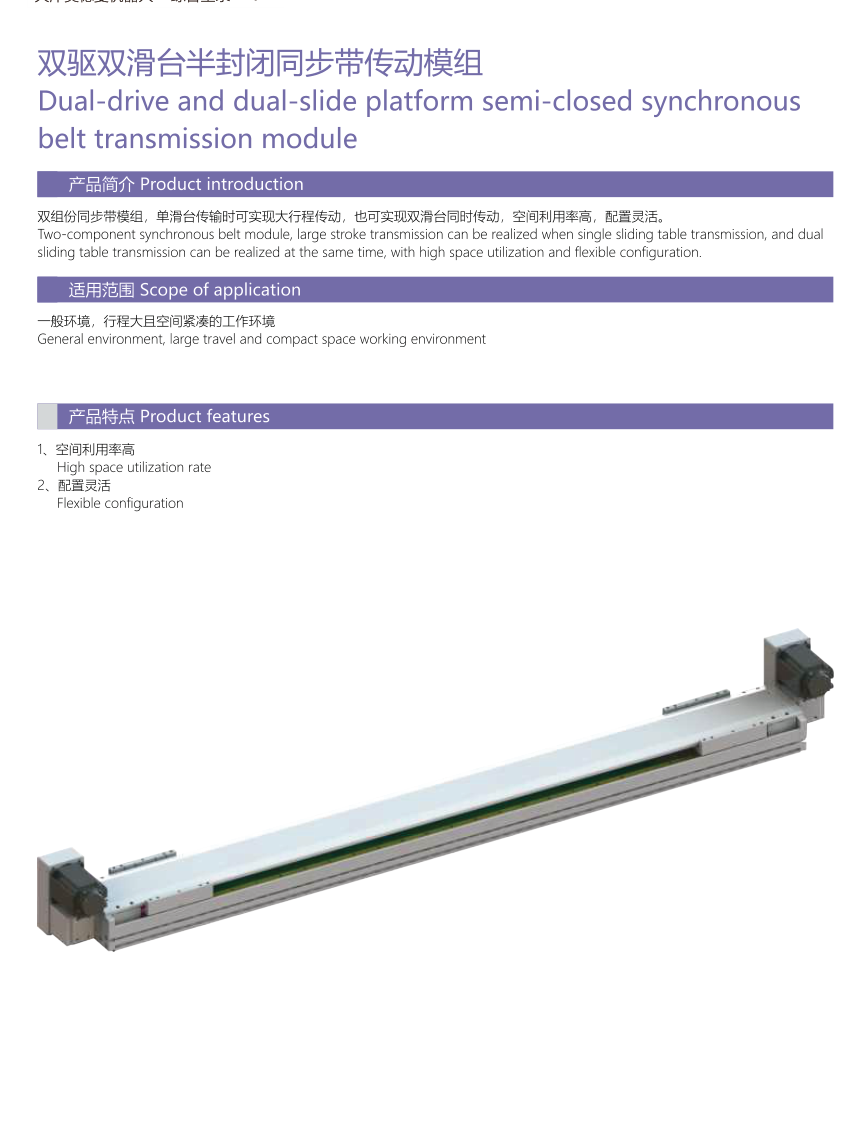
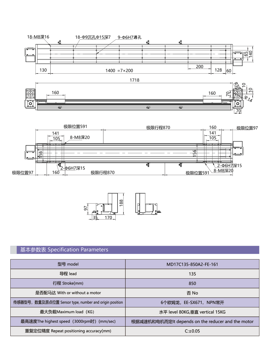
Dual-drive/dual-slide semi-closed synchronous belt
Independent illustrated project, no inferred speed from lead. Model | MD17C135-850A2-FE-161 Lead | 135; unit not printed Stroke | 850mm Motor | No Sensors | 6 EE-SX671,NPN Maximum load | horizontal80kg;vertical15kg Max speed at3000rpm | depends on reducer and motor Repeatability | C:±0.05; unit not printed
Modman linear-motor application references
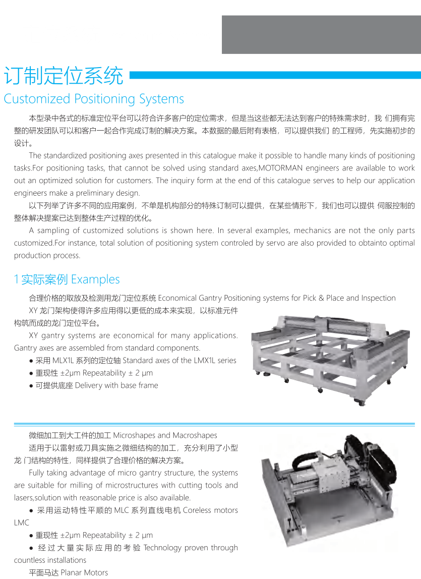
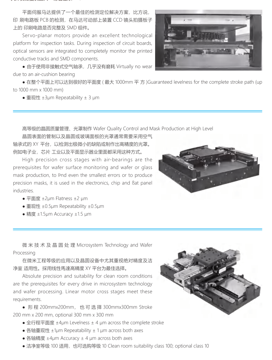
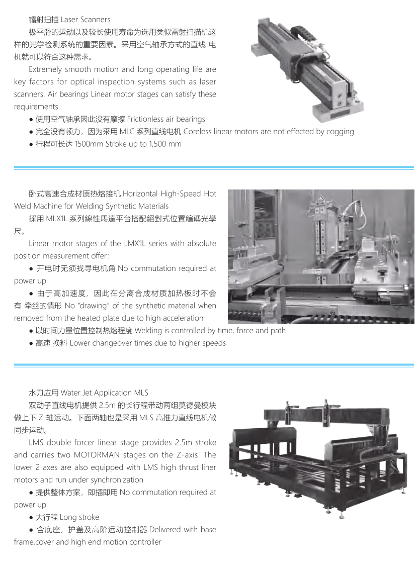
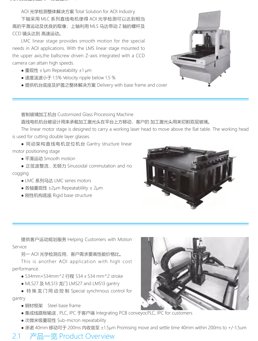
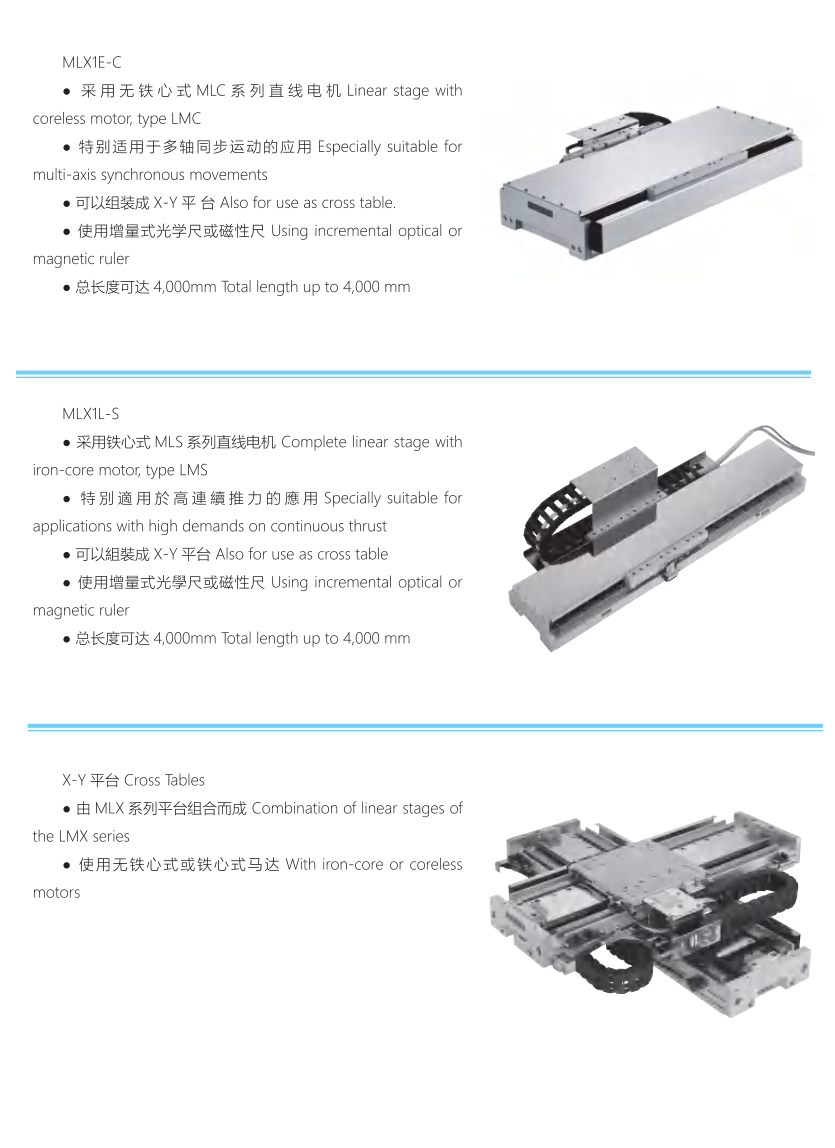
Original customized positioning references: economic gantry±2μm; microstructure/macrostructure machining with coreless MLC/LMC±2μm; PCB/SMT inspection, flatness within1m×1m and repeatability±3μm; glass-mask/wafer processing flatness±2μm, repeatability±0.5μm, accuracy±1.5μm; clean micromachining200×200mm(option300×300), levelness±4μm and both-axis accuracy±4μm, source clean-room100(option10). Laser-scanner frictionless/coreless stages up to1500mm; hot-welding LMX1L systems with absolute feedback; water-jet LMS dual drive2.5m stroke. AOI example: MLC lower axis±1μm and speed ripple<1.5%, upper MLS Z/CCD; customized glass gantry±2μm; another AOI534×534mm, MLS27/MLS13,40mm in200ms to±1.5μm. LMX1E-C coreless MLC/LMX1L-S LMS variants state total length up to4000mm. Keep each application condition independent; none is an HTROBOT performance promise or inheritance into TKP.
Modman safety, commissioning and guarded operation
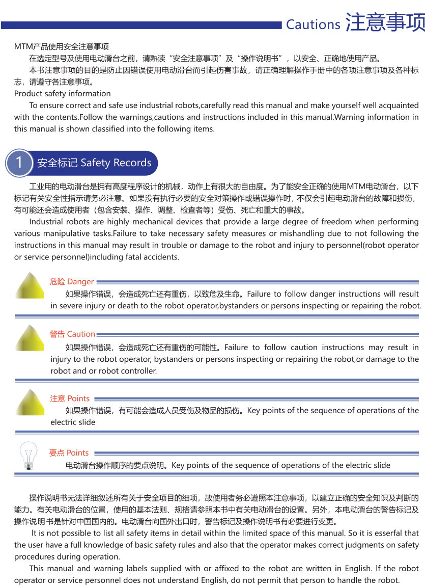
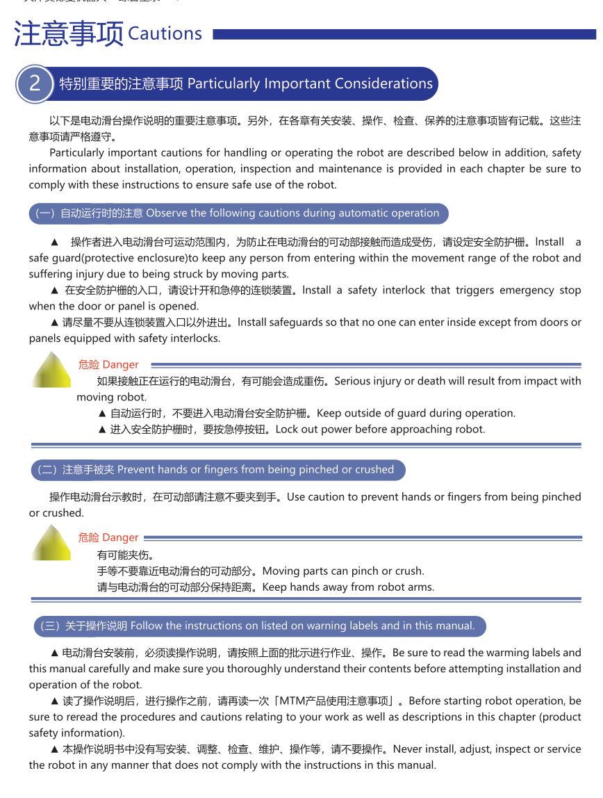
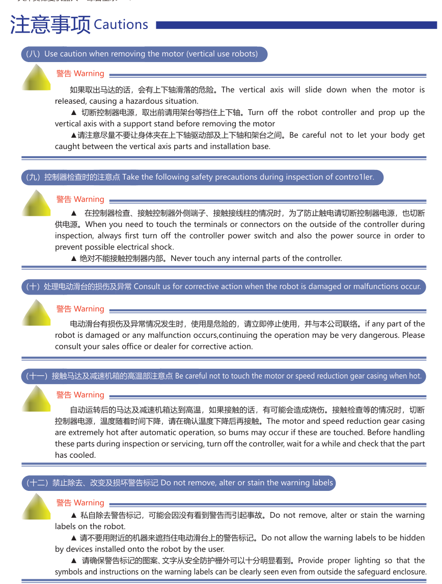
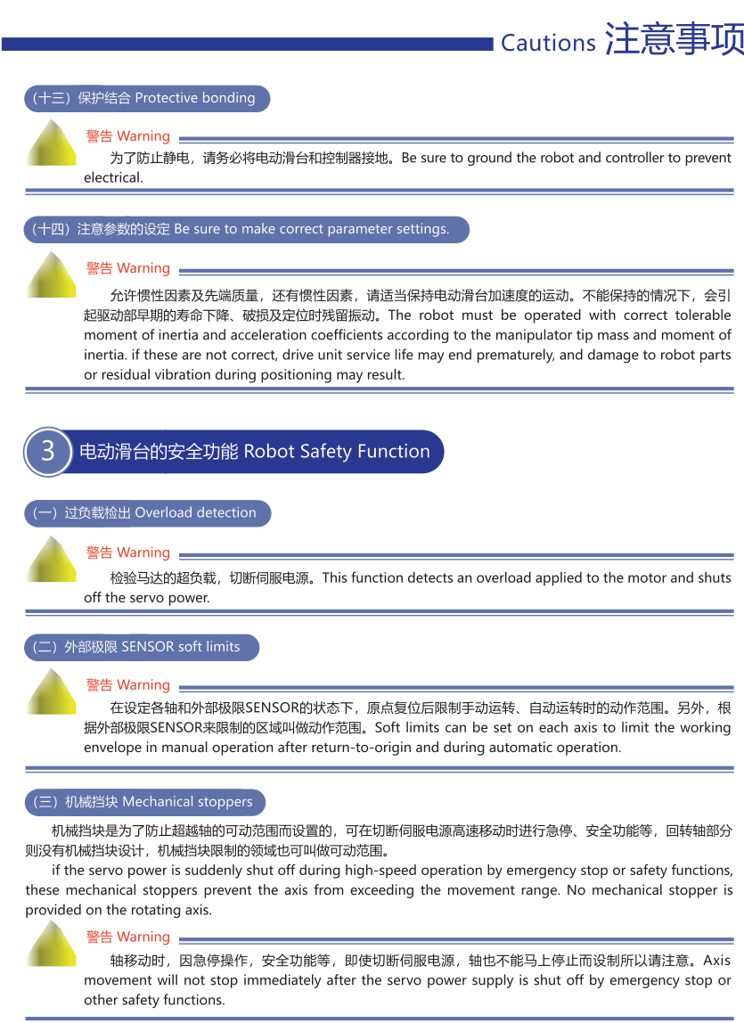
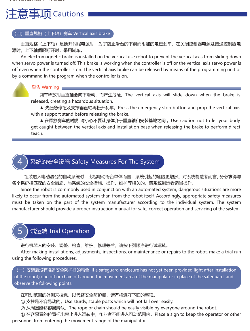
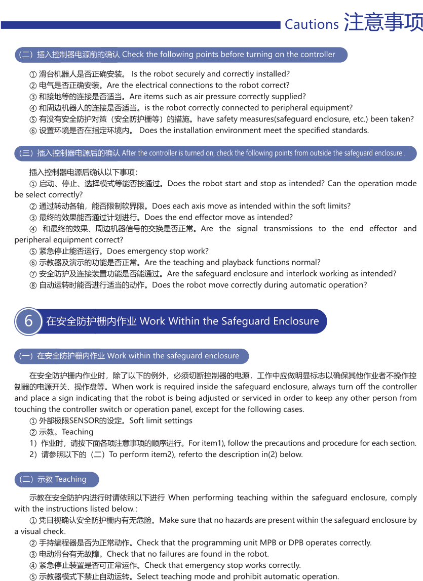
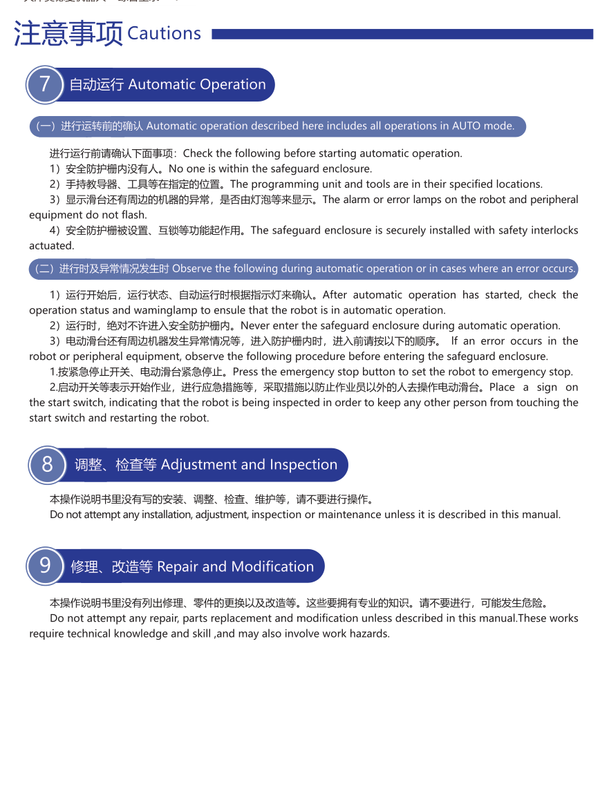
Original printed409–416 is MTM safety guidance, not a flange-motor chapter. Preserve danger/warning distinction, guarded motion enclosure and interlocked emergency stop; prevent hands/fingers entering moving parts; no flammable/explosive/water/corrosive-gas or electromagnetic-interference operation. Vertical axes require support when brakes/motors are released or removed. Isolate controller power before cable work, inspection and motor removal; avoid residual hot motor/reducer surfaces; ground/protective-bond equipment. Preserve warning signs and lighting. Check permissible load, acceleration, drive service life and motor parameters. Overload detection, sensor soft limits and mechanical stoppers are separate functions; stoppers/axis brakes do not replace system safety measures. Before commissioning check mounting, power, peripheral connections, guards and installation environment. Test stopping/motion/softlimits/encoders/peripheral signals/emergency stop, teach and playback, enclosure interlock and automatic operation. Work/teaching inside guards requires the source isolation and controlled-mode procedures. The original references are not a complete machine safety design or certification.
Modman original request checklist
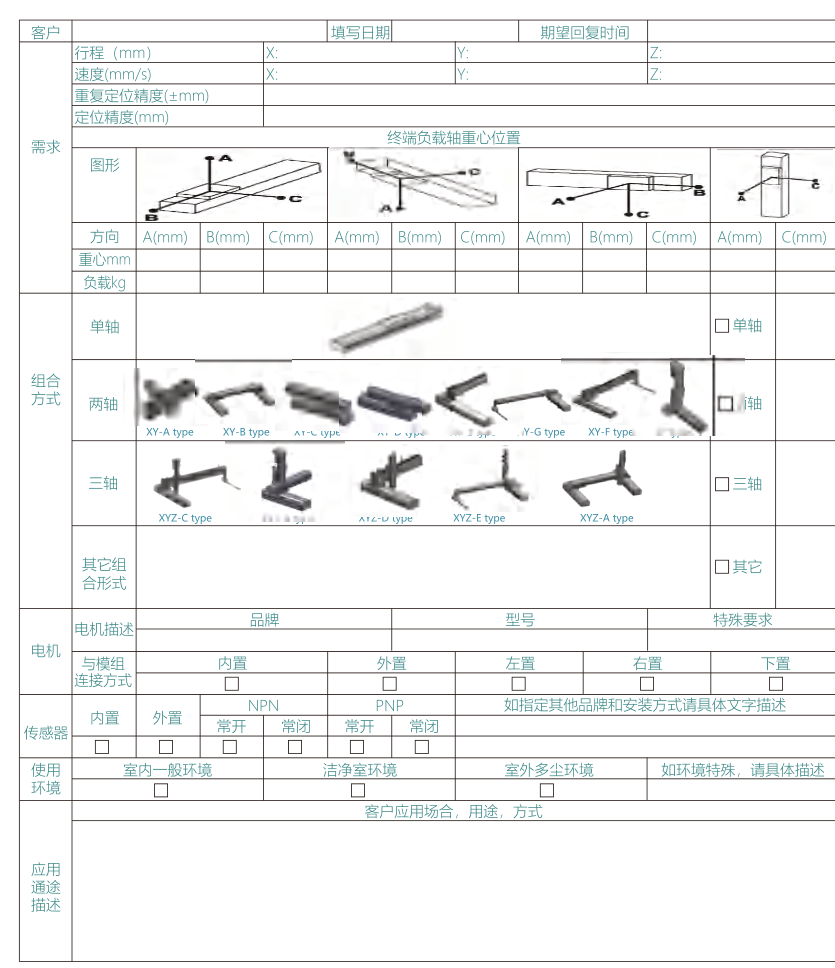
Original empty request form records axis arrangement/mounting and offset distances, effective travel, load and weight, speed, repeatability/positioning accuracy, motor brand/model/special requirements, mounting direction, sensors and NPN/PNP signals, environmental conditions and application description. It is an input checklist only; no supplier contact or submission endpoint is carried into the site, and the form does not create a business record.
Related product and selection paths
Add this topic to inquiry
Saved in this browser only. Nothing is sent.