
Technical article
Ball screw or belt drive for a linear module?
Learn the main motion tradeoffs, then compare complete ball-screw and belt-driven module configurations.
Move from drive type to a model
Use the MF ball-screw family and MDK belt-driven platform as two starting points. Compare the same usable travel, load and orientation before choosing a drive. A family label alone does not establish which model meets the task.
Keep each comparison together
Read speed, load and positioning values with the screw lead, installation direction and other conditions attached to their source row. For a vertical axis, include the load-holding and brake requirements in the equipment proposal.
Continue comparing
Start with the same task and measurement basis
Record the usable stroke, carried load and offset, target speed and cycle, positioning and repeatability needs, installation direction and available space. Compare candidate modules against the same requirements.
Compare the actual configurations
A ball screw turns to advance a nut and carriage. A toothed belt moves the carriage between pulleys. Belt units are often considered for longer travel and faster motion; screw units are often considered when stiffness and positioning control matter. Supported screws can also serve demanding travel and speed, so check the actual model data.
| Comparison point | Ball screw | Belt drive |
|---|---|---|
| How it moves | A rotating screw advances a nut and carriage. | A toothed belt carries the carriage between pulleys. |
| Typical starting point | Review when stiffness and controlled positioning are central. | Review when long travel and rapid motion are central. |
| What to check | Lead, support, backlash, load and lubrication on the selected model. | Belt tension and stiffness, load, travel and service access on the selected model. |
Treat vertical motion as a separate safety question
For a vertical axis, specify what must hold the load during a stop, power loss or transmission failure. Ask how the brake and protective design work with the complete drive and controller.
Request the exact axis proposal
Send the requirements and review one model and configuration at a time: its mounting drawing, travel, speed, load, positioning data and service needs. The MF and MD family links below are places to begin the comparison.
Catalogue engineering references
MKK motor seats and flange ordering references
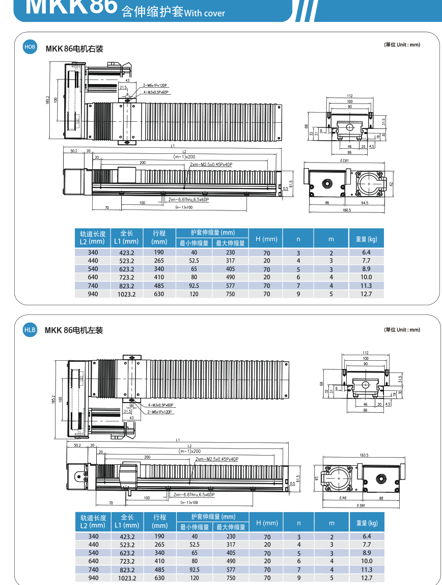
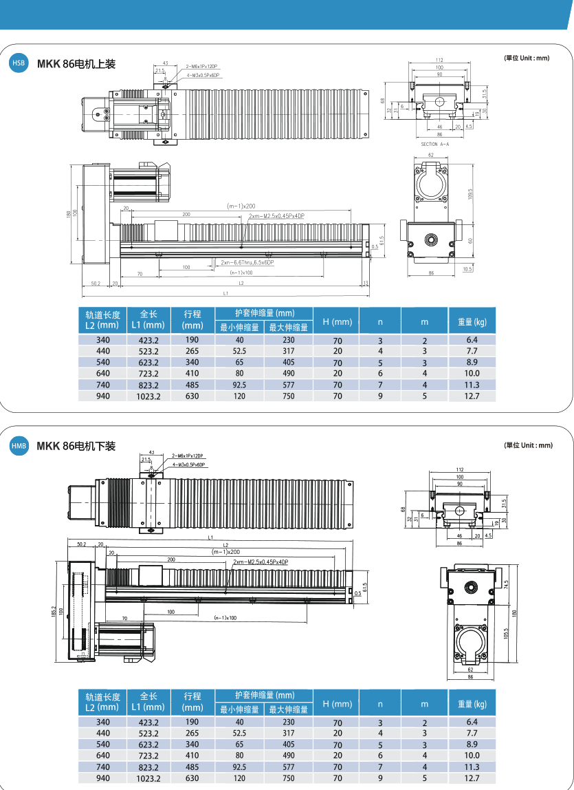
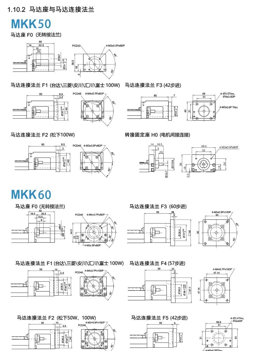
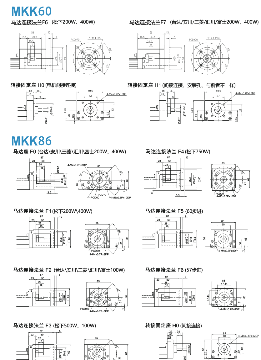
Original p.88–89 references, separate from the already consumed MKK primary tables. MKK50: F0 without flange; F1 Delta/Mitsubishi/Yaskawa/Inovance/Fuji 100W; F2 Panasonic 100W; F3 42 stepper; H0 coupling connection. MKK60: F0 without flange; F1 Delta/Mitsubishi/Yaskawa/Inovance/Fuji 100W; F2 Panasonic 50W/100W; F3 60 stepper; F4 57 stepper; F5 42 stepper; F6 Panasonic 200W/400W; F7 Delta/Mitsubishi/Yaskawa/Inovance/Fuji 200W/400W; H0 coupling connection; H1 indirect connection for mounting/drilling spindles. MKK86: F0 Delta/Mitsubishi/Yaskawa/Inovance/Fuji 200W/400W; F1 Panasonic 200W/400W; F2 Delta/Mitsubishi/Yaskawa/Inovance/Fuji 100W; F3 Panasonic 750W/1000W; F4 Panasonic 750W; F5 60 stepper; F6 57 stepper; H0 coupling connection. Source F3/F4 power overlap is retained, not resolved by substitution. Mount drawings and covered MKK86 HB/HL/HS/HW installation drawings remain independently referenced; this is not a CAD clearance approval.
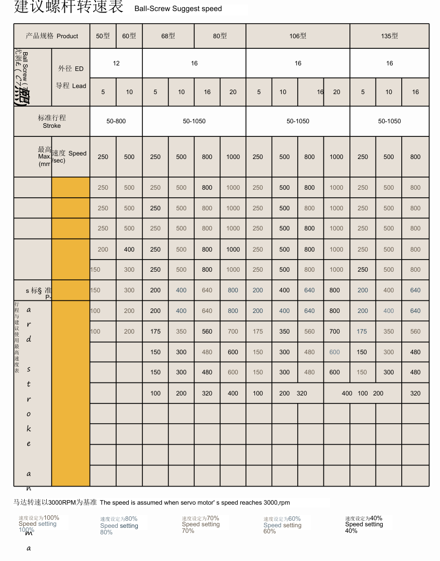
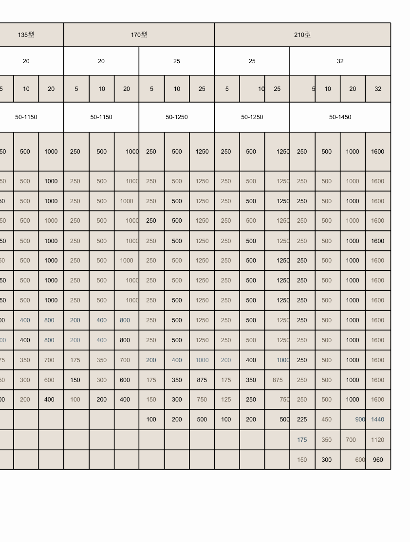
Tuogu screw-speed reference grid
Original screw-speed reference, assumed servo speed 3000rpm. Columns are generic sizes50/60/68/80/106/135(left),135/170/210(right), grouped by screw diameter and lead. Values have printed speed unit mm/sec. Percentage legend100/80/70/60/40 is retained separately. The supplied original has missing stroke row labels: row position cannot establish an exact stroke or numeric selection condition. Values must not become model ratings, and the TK68-specific confirmed32mm erratum remains effective. left row0: 250, 500, 250, 500, 800, 1000, 250, 500, 800, 1000, 250, 500, 800 left row1: 250, 500, 250, 500, 800, 1000, 250, 500, 800, 1000, 250, 500, 800 left row2: 250, 500, 250, 500, 800, 1000, 250, 500, 800, 1000, 250, 500, 800 left row3: 250, 500, 250, 500, 800, 1000, 250, 500, 800, 1000, 250, 500, 800 left row4: 200, 400, 250, 500, 800, 1000, 250, 500, 800, 1000, 250, 500, 800 left row5: 150, 300, 250, 500, 800, 1000, 250, 500, 800, 1000, 250, 500, 800 left row6: 150, 300, 200, 400, 640, 800, 200, 400, 640, 800, 200, 400, 640 left row7: 100, 200, 200, 400, 640, 800, 200, 400, 640, 800, 200, 400, 640 left row8: 100, 200, 175, 350, 560, 700, 175, 350, 560, 700, 175, 350, 560 left row9: 150, 300, 480, 600, 150, 300, 480, 600, 150, 300, 480 [remaining source cells blank] left row10: 150, 300, 480, 600, 150, 300, 480, 600, 150, 300, 480 [remaining source cells blank] left row11: 100, 200, 320, 400, 100, 200, 320, 400, 100, 200, 320 [remaining source cells blank] left row12: [remaining source cells blank] left row13: [remaining source cells blank] left row14: [remaining source cells blank] left row15: [remaining source cells blank] right row0: 250, 500, 1000, 250, 500, 1000, 250, 500, 1250, 250, 500, 1250, 250, 500, 1000, 1600 right row1: 250, 500, 1000, 250, 500, 1000, 250, 500, 1250, 250, 500, 1250, 250, 500, 1000, 1600 right row2: 250, 500, 1000, 250, 500, 1000, 250, 500, 1250, 250, 500, 1250, 250, 500, 1000, 1600 right row3: 250, 500, 1000, 250, 500, 1000, 250, 500, 1250, 250, 500, 1250, 250, 500, 1000, 1600 right row4: 250, 500, 1000, 250, 500, 1000, 250, 500, 1250, 250, 500, 1250, 250, 500, 1000, 1600 right row5: 250, 500, 1000, 250, 500, 1000, 250, 500, 1250, 250, 500, 1250, 250, 500, 1000, 1600 right row6: 250, 500, 1000, 250, 500, 1000, 250, 500, 1250, 250, 500, 1250, 250, 500, 1000, 1600 right row7: 250, 500, 1000, 250, 500, 1000, 250, 500, 1250, 250, 500, 1250, 250, 500, 1000, 1600 right row8: 200, 400, 800, 200, 400, 800, 250, 500, 1250, 250, 500, 1250, 250, 500, 1000, 1600 right row9: 200, 400, 800, 200, 400, 800, 250, 500, 1250, 250, 500, 1250, 250, 500, 1000, 1600 right row10: 175, 350, 700, 175, 350, 700, 200, 400, 1000, 200, 400, 1000, 250, 500, 1000, 1600 right row11: 150, 300, 600, 150, 300, 600, 175, 350, 875, 175, 350, 875, 250, 500, 1000, 1600 right row12: 100, 200, 400, 100, 200, 400, 150, 300, 750, 125, 250, 750, 250, 500, 1000, 1600 right row13: 100, 200, 500, 100, 200, 500, 225, 450, 900, 1440 [remaining source cells blank] right row14: 175, 350, 700, 1120 [remaining source cells blank] right row15: 150, 300, 600, 960 [remaining source cells blank]
Tuogu selection conditions and life calculation
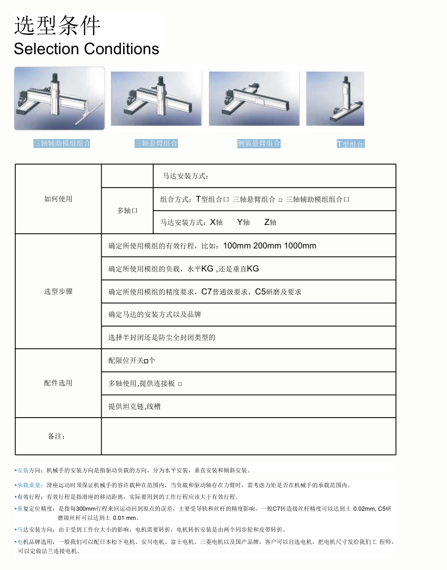
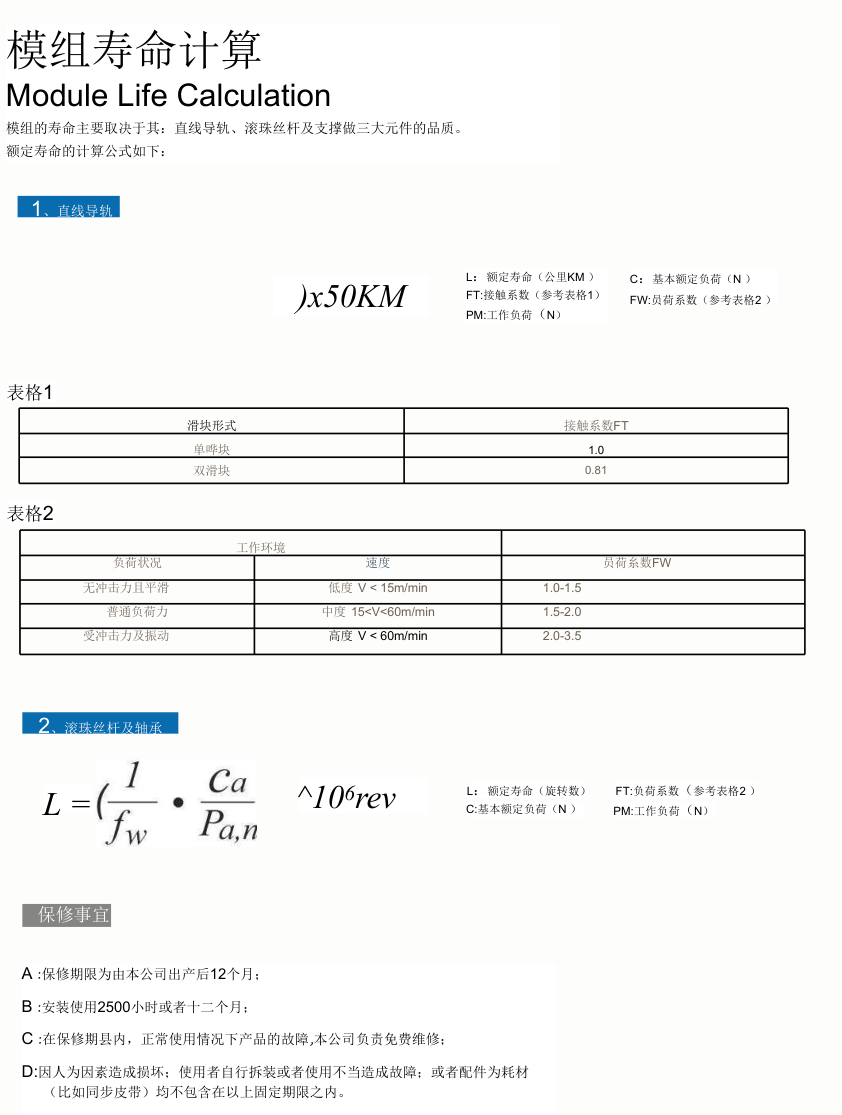
Selection inputs: axis arrangement and mounting, X/Y/Z direction, effective stroke, horizontal/vertical load, accuracy grade(C7 general/C5 higher precision), motor/drive choice, switches, multi-axis interfaces, cables and drag chains. Original life formulas distinguish linear guides from screws/support bearings; the first supplied formula has damaged/missing symbols, so no repaired exponent or calculated life is offered. The screw/bearing formula shows L, fw, Ca, Pa,n and10^6rev; damaged typesetting does not establish every exponent. Symbols and load conditions must be verified against the original figure before calculation. Original contact factors: single slider1.0, double slider0.81. Operating factors: no-impact very-low-speed V<15m/min1.0–1.5; medium-speed15<V<60m/min1.5–2.0; high-speed V>60m/min2.0–3.5. These are source methodology references, not a warranty or application-specific life estimate.
Modman linear-stage construction and delivery
Direct drive, internal cable chain, guide system, travel limit switches and optional covers. Original p.401 delivery distinguishes serialRS232, analog±10V, pulse/direction and other interfaces; main cables are power, encoder and limit-switch. Mounting may be horizontal or vertical with different chain orientations. Structure includes force plate/forcer, guide blocks/rails, encoder, motor connector, stopping buffer, limit switches1/2, stator and base. General specifications(mm/300mm): LMX1E- MLC±0.001 repeatability,±0.005 accuracy,±0.005 straightness,±0.005 flatness; MLX1L-S LMS±0.001,±0.005,±0.005,±0.005; MLX1L-SC MLSC±0.001,±0.005,±0.005,±0.005; MLX1L- MLT±0.002,±0.010,±0.005,±0.005. Maximum operating voltages: LMS/MLT500VAC, MLC500VDC. Accuracy uses40μm grating pitch and stroke below500mm, with HIWIN compensation technology. Mixed spelling LMX/MLX remains source-specific.
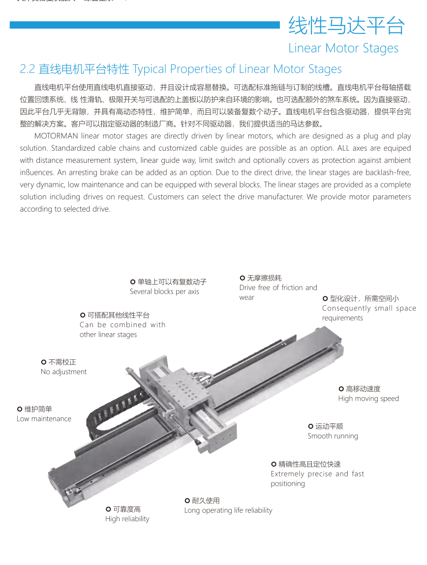
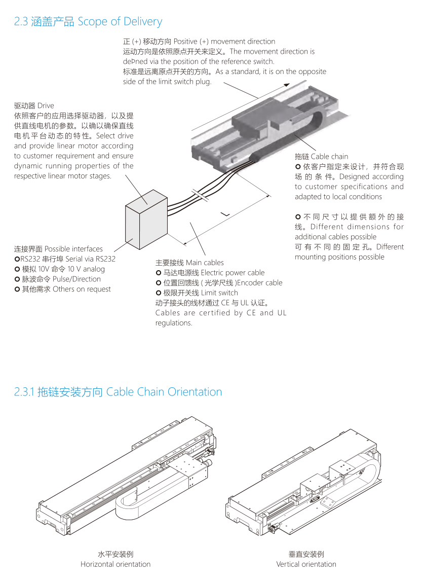
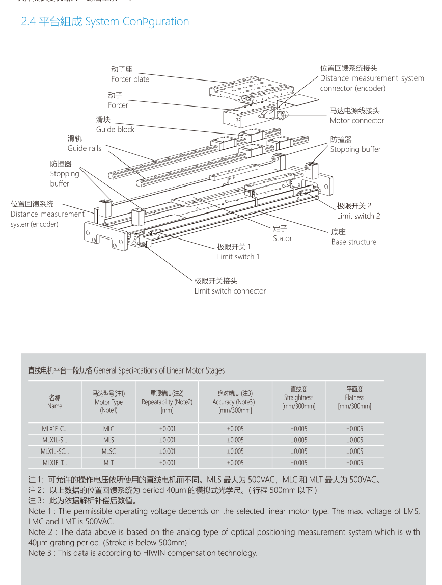
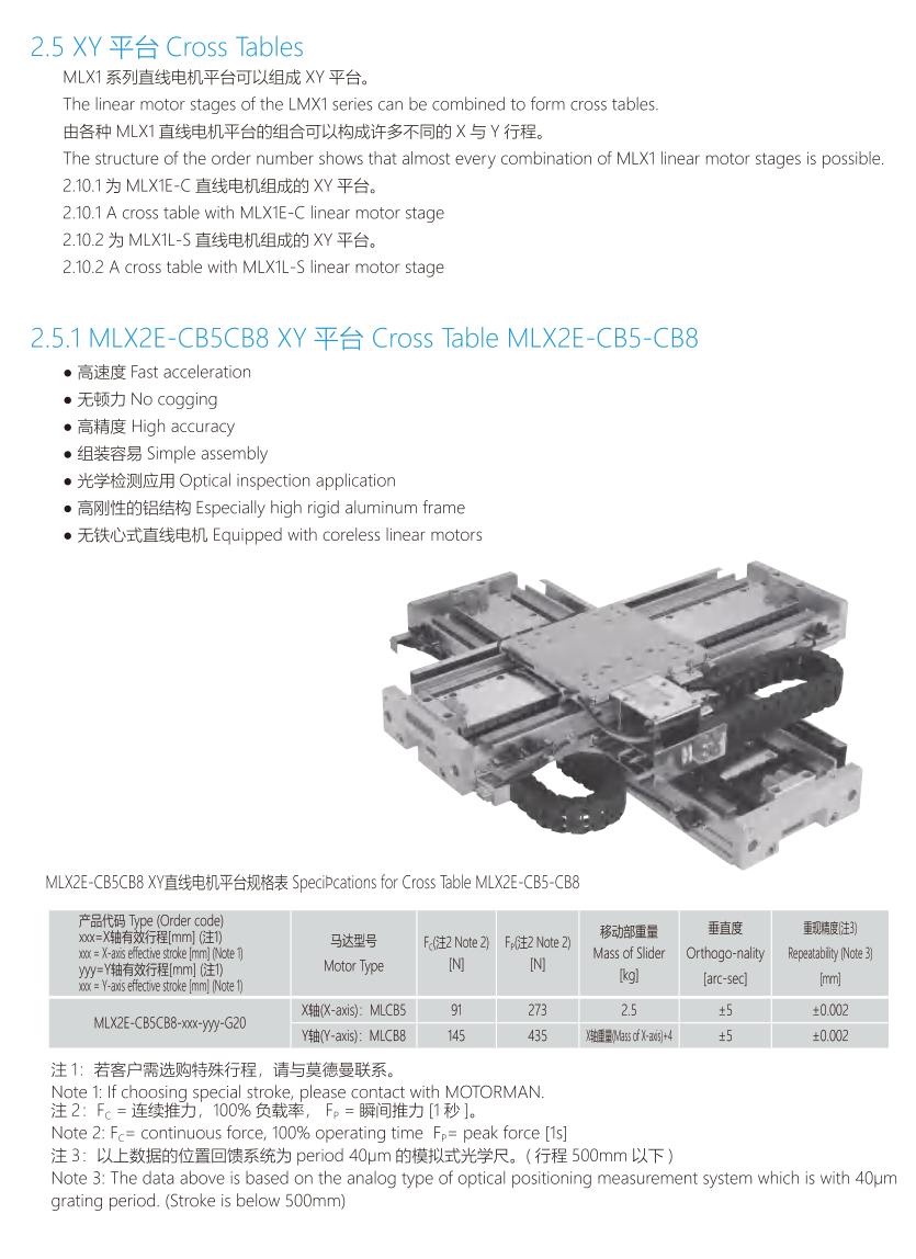
Modman XY platform main specifications
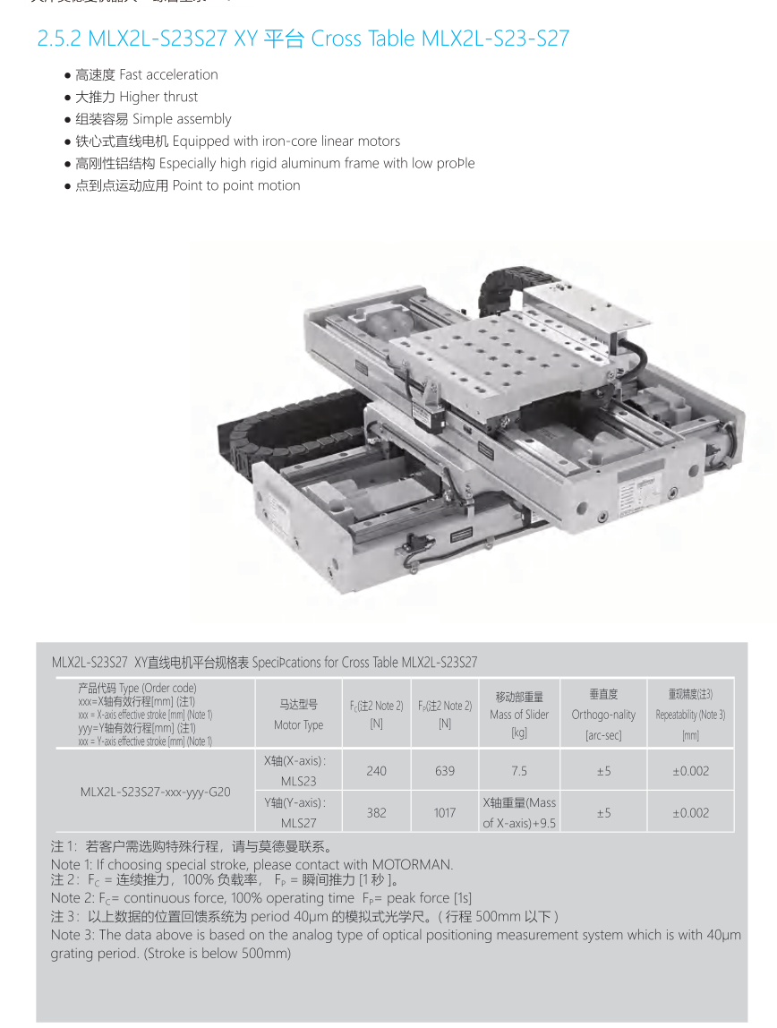
MLX2E-CB5CB8 coreless MLC platform: X MLCB5 continuous-force91N,peak273N,X mass2.5kg,orthogonality±5arc-sec,repeatability±0.002mm; Y MLCB8 continuous145N,peak435N,Y mass = X-axis mass+4kg; keep X/Y axis rows independent. MLX2L-S23S27 iron-core MLS platform: X MLS23 continuous240N,peak639N,X mass7.5kg,orthogonality±5arc-sec,repeatability±0.002mm; Y MLS27 continuous382N,peak1017N,Y mass = X-axis mass+9.5kg. Notes: continuous force uses100% duty; peak-force time1s; accuracy uses40μm grating pitch and stroke below500mm. Platforms are source reference objects only, not eight existing Tuogu coils or new catalogue models.
MLX2E-CB5CB8 covered/uncovered schedules
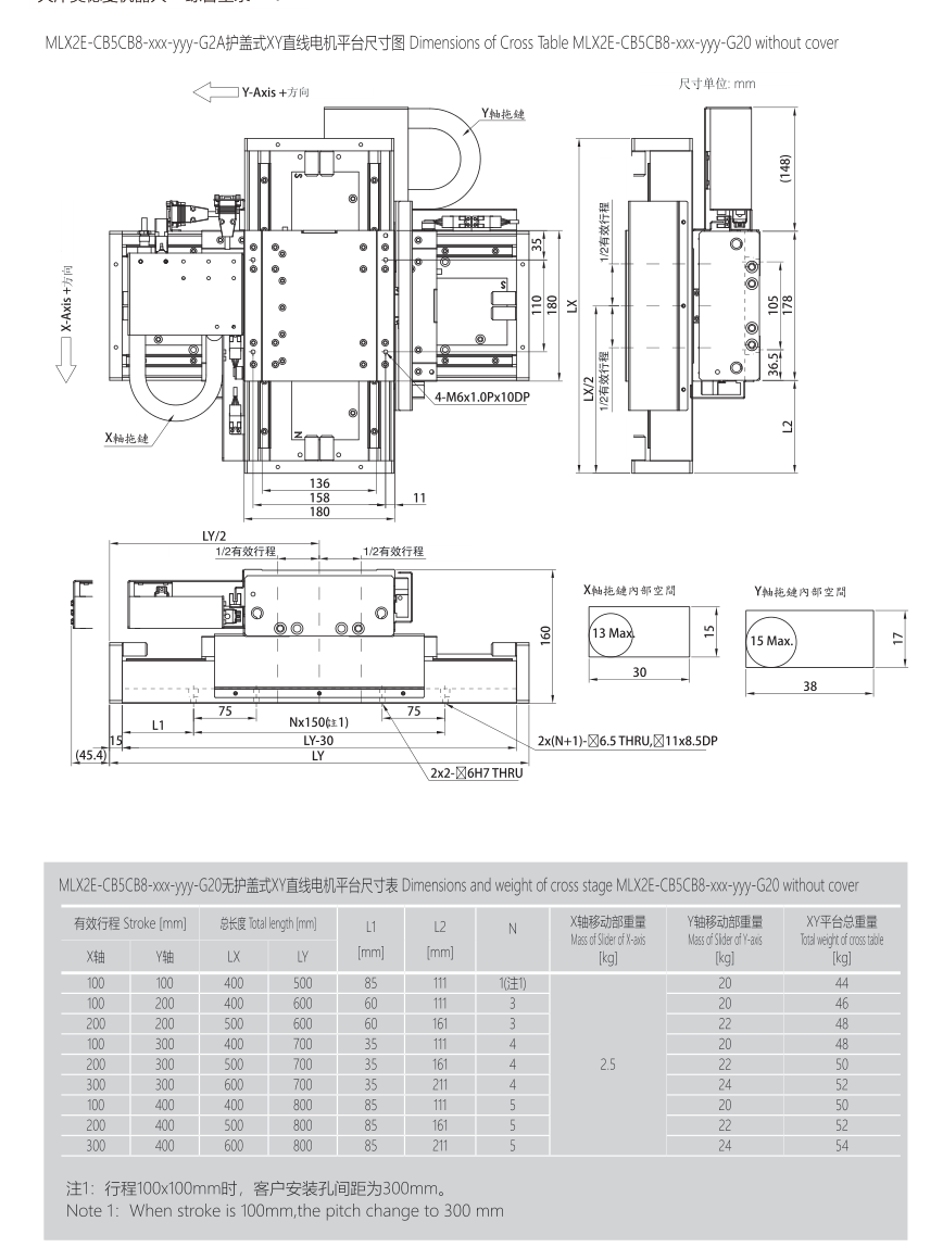
Separate original -G2O(uncovered) and -G2A(covered) schedules; source zero/O suffix typography retained in native figures. Each variant prints the following nine rows. Dimensionsmm, masskg, N hole count; source first N row carries Note1. Stroke100×100mm note changes customer mounting-hole pitch300mm. X mass is a merged source column, repeated here only to make each row self-contained. No transfer to existing-model configurations. StrokeX(mm) | StrokeY(mm) | LX(mm) | LY(mm) | L1(mm) | L2(mm) | N | Xmass(kg) | Ymass(kg) | XYmass(kg) 100 | 100 | 400 | 500 | 85 | 111 | 1 | 2.5 | 20 | 44 100 | 200 | 400 | 600 | 60 | 111 | 3 | 2.5 | 20 | 46 200 | 200 | 500 | 600 | 60 | 161 | 3 | 2.5 | 22 | 48 100 | 300 | 400 | 700 | 35 | 111 | 4 | 2.5 | 20 | 48 200 | 300 | 500 | 700 | 35 | 161 | 4 | 2.5 | 22 | 50 300 | 300 | 600 | 700 | 35 | 211 | 4 | 2.5 | 24 | 52 100 | 400 | 400 | 800 | 85 | 111 | 5 | 2.5 | 20 | 50 200 | 400 | 500 | 800 | 85 | 161 | 5 | 2.5 | 22 | 52 300 | 400 | 600 | 800 | 85 | 211 | 5 | 2.5 | 24 | 54
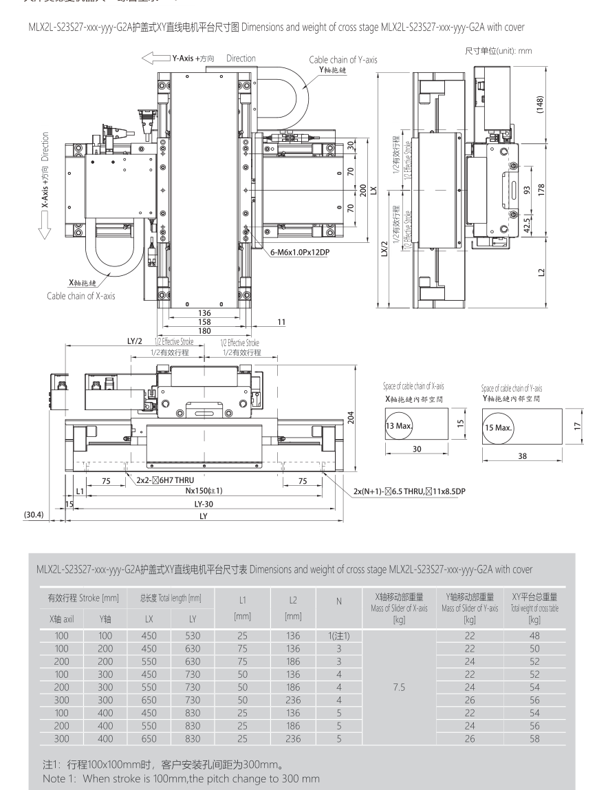
MLX2L-S23S27 covered/uncovered schedules
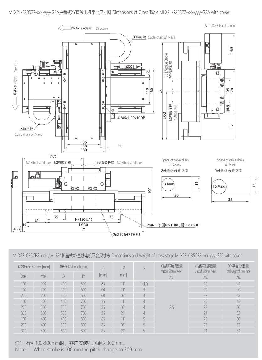
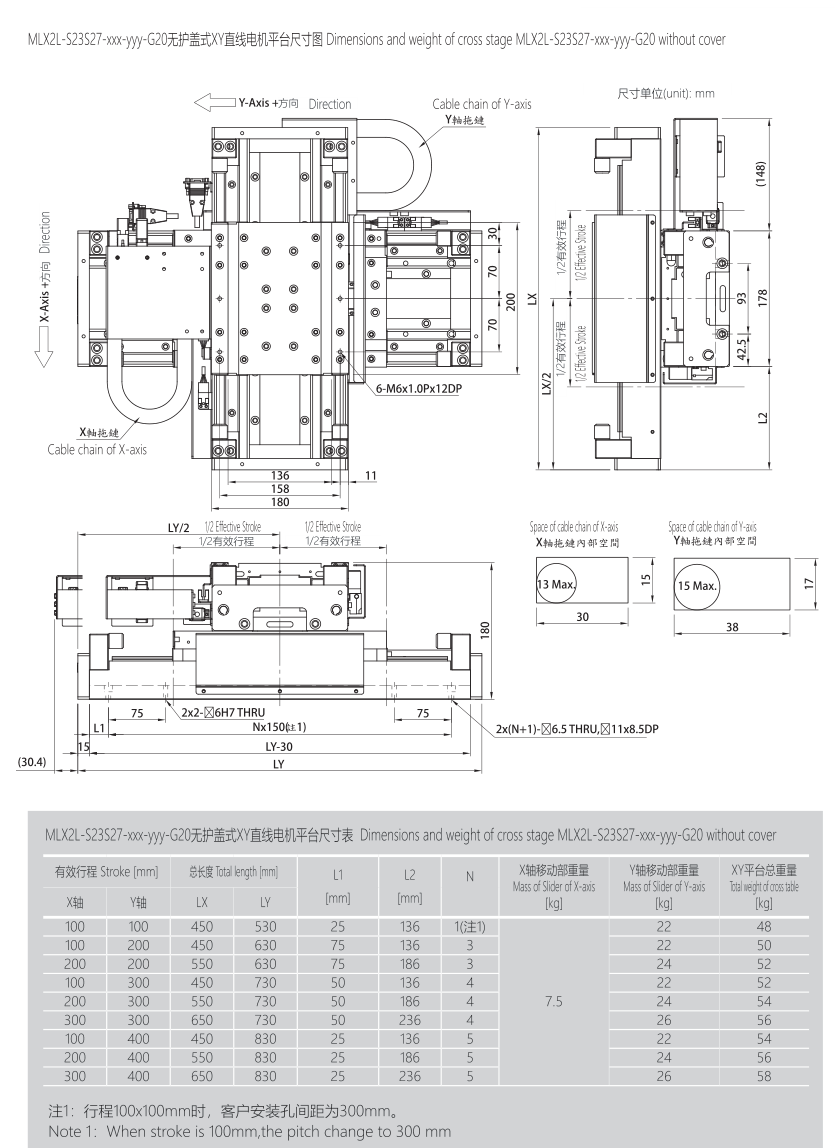
Separate original -G2O(uncovered) and -G2A(covered) schedules; source zero/O suffix typography retained in native figures. Each variant prints the following nine rows. Dimensionsmm, masskg, N hole count; source first N row carries Note1. Stroke100×100mm note changes customer mounting-hole pitch300mm. X mass is a merged source column, repeated here only to make each row self-contained. No transfer to existing-model configurations. StrokeX(mm) | StrokeY(mm) | LX(mm) | LY(mm) | L1(mm) | L2(mm) | N | Xmass(kg) | Ymass(kg) | XYmass(kg) 100 | 100 | 450 | 530 | 25 | 136 | 1 | 7.5 | 22 | 48 100 | 200 | 450 | 630 | 75 | 136 | 3 | 7.5 | 22 | 50 200 | 200 | 550 | 630 | 75 | 186 | 3 | 7.5 | 24 | 52 100 | 300 | 450 | 730 | 50 | 136 | 4 | 7.5 | 22 | 52 200 | 300 | 550 | 730 | 50 | 186 | 4 | 7.5 | 24 | 54 300 | 300 | 650 | 730 | 50 | 236 | 4 | 7.5 | 26 | 56 100 | 400 | 450 | 830 | 25 | 136 | 5 | 7.5 | 22 | 54 200 | 400 | 550 | 830 | 25 | 186 | 5 | 7.5 | 24 | 56 300 | 400 | 650 | 830 | 25 | 236 | 5 | 7.5 | 26 | 58
Related product and selection paths
Add this topic to inquiry
Saved in this browser only. Nothing is sent.