
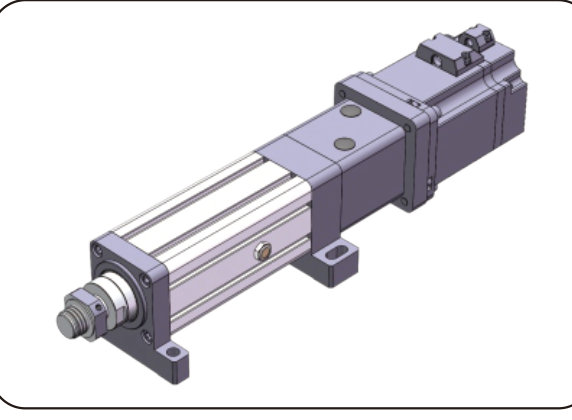
Electric cylinders · High-precision, high-load servo electric cylinder with customizable stroke
EDA300High-precision, high-load servo electric cylinder with customizable stroke · EDA300
EDA300 belongs to High-precision, high-load servo electric cylinder with customizable stroke in the Electric cylinders catalog.
EDA300 · Electric cylinders and linear actuators
An electric cylinder supplies a guided extension motion. Prepare the required thrust, stroke, speed, working cycle and load connection as one assembly requirement.
Comparing EDA300
For EDA300, read Accuracy Positioning | accuracy level, Ball diameter, Ball screw rigidity by the parameter group and variant shown. Compare screw and connection drawings for the proposed assembly. Check thrust, extension and speed together; separate upper limits do not establish a usable operating point.
Parameters and where they apply
| Accuracy Positioning | accuracy level Source condition; not yet structured · (Note: The parameters of the ball screw are applicable to strokes ≤ 300mm. For strokes greater than 300mm, please consult our technical personnel.) · Current technical model · Ball screw parameters; Source row: JF10020-8; Source column: Accuracy Positioning | accuracy level | C5/±0.01 |
|---|---|
| Accuracy Positioning | accuracy level Source condition; not yet structured · (Note: The parameters of the ball screw are applicable to strokes ≤ 300mm. For strokes greater than 300mm, please consult our technical personnel.) · Current technical model · Ball screw parameters; Source row: JF10020-8; Source column: Accuracy Positioning | accuracy level | C7/±0.02 |
| Ball diameter Source condition; not yet structured · (Note: The parameters of the ball screw are applicable to strokes ≤ 300mm. For strokes greater than 300mm, please consult our technical personnel.) · Current technical model · Ball screw parameters; Source row: JF10020-8; Source column: Ball diameter | 12.7mm mm |
| Ball diameter Source condition; not yet structured · (Note: The parameters of the ball screw are applicable to strokes ≤ 300mm. For strokes greater than 300mm, please consult our technical personnel.) · Current technical model · Ball screw parameters; Source row: JF10025-8; Source column: Ball diameter | 15.875mm mm |
| Ball screw rigidity Source condition; not yet structured · (Note: The parameters of the ball screw are applicable to strokes ≤ 300mm. For strokes greater than 300mm, please consult our technical personnel.) · Current technical model · Ball screw parameters; Source row: JF10020-8; Source column: Ball screw rigidity | / |
| Ball screw rigidity Source condition; not yet structured · (Note: The parameters of the ball screw are applicable to strokes ≤ 300mm. For strokes greater than 300mm, please consult our technical personnel.) · Current technical model · Ball screw parameters; Source row: JF10025-8; Source column: Ball screw rigidity | / |
| Ca (KN) Source condition; not yet structured · (Note: The parameters of the ball screw are applicable to strokes ≤ 300mm. For strokes greater than 300mm, please consult our technical personnel.) · Current technical model · Ball screw parameters; Source row: JF10020-8; Source column: Ca (KN) | 444.9 KN |
| Ca (KN) Source condition; not yet structured · (Note: The parameters of the ball screw are applicable to strokes ≤ 300mm. For strokes greater than 300mm, please consult our technical personnel.) · Current technical model · Ball screw parameters; Source row: JF10025-8; Source column: Ca (KN) | 603.3 KN |
| Center distance of synchronous wheel Current technical model · Synchronous wheel and synchronous belt:; Source row: 1:1; Source column: Center distance of synchronous wheel | 280mm mm |
| Coa (KN) Source condition; not yet structured · (Note: The parameters of the ball screw are applicable to strokes ≤ 300mm. For strokes greater than 300mm, please consult our technical personnel.) · Current technical model · Ball screw parameters; Source row: JF10020-8; Source column: Coa (KN) | 1526.9 KN |
| Coa (KN) Source condition; not yet structured · (Note: The parameters of the ball screw are applicable to strokes ≤ 300mm. For strokes greater than 300mm, please consult our technical personnel.) · Current technical model · Ball screw parameters; Source row: JF10025-8; Source column: Coa (KN) | 1891.2 KN |
| Cor (KN) Current technical model · Bearing parameters:; Source row: Deep groove ball 6217-ZZx2; Source column: Cor (KN) | 63.8 KN |
| Cor (KN) Current technical model · Bearing parameters:; Source row: Thrust self-aligning roller bearing 29417; Source column: Cor (KN) | 1730 KN |
| Cr (KN) Current technical model · Bearing parameters:; Source row: Deep groove ball 6217-ZZx2; Source column: Cr (KN) | 83.3 KN |
| Cr (KN) Current technical model · Bearing parameters:; Source row: Thrust self-aligning roller bearing 29417; Source column: Cr (KN) | 600 KN |
| Diameter Source condition; not yet structured · (Note: The parameters of the ball screw are applicable to strokes ≤ 300mm. For strokes greater than 300mm, please consult our technical personnel.) · Current technical model · Ball screw parameters; Source row: JF10020-8; Source column: Diameter | 100 mm mm |
| Driven gear specifications Current technical model · Synchronous wheel and synchronous belt:; Source row: 1:1; Source column: Driven gear specifications | 14M50T86 T |
| Driving gear specifications Current technical model · Synchronous wheel and synchronous belt:; Source row: 1:1; Source column: Driving gear specifications | 14M50T86 T |
| Lead of ball screw Source condition; not yet structured · (Note: The parameters of the ball screw are applicable to strokes ≤ 300mm. For strokes greater than 300mm, please consult our technical personnel.) · Current technical model · Ball screw parameters; Source row: JF10020-8; Source column: Lead of ball screw | 20mm mm |
| Lead of ball screw Source condition; not yet structured · (Note: The parameters of the ball screw are applicable to strokes ≤ 300mm. For strokes greater than 300mm, please consult our technical personnel.) · Current technical model · Ball screw parameters; Source row: JF10025-8; Source column: Lead of ball screw | 25mm mm |
| Limit switch Source condition; not yet structured · (Note: Thrust, stroke, and speed should be combined with actual usage, and the upper limit values of the three cannot be used together.) · Current technical model · Basic parameters:; Source row: Φ280 mm; Source column: Limit switch | Proximity switch |
| Maximum allowed speed Source condition; not yet structured · (Note: Thrust, stroke, and speed should be combined with actual usage, and the upper limit values of the three cannot be used together.) · Current technical model · Basic parameters:; Source row: Φ280 mm; Source column: Maximum allowed speed Rotation angle of piston rod | ≤250 mm/s mm/s |
| Maximum thrust allowed Source condition; not yet structured · (Note: Thrust, stroke, and speed should be combined with actual usage, and the upper limit values of the three cannot be used together.) · Current technical model · Basic parameters:; Source row: Φ280 mm; Source column: Maximum thrust allowed | ≤600KN KN |
| Motor specifications that can be directly installed Current technical model · Optional configuration:; Source row: 20mm; Source column: Motor specifications that can be directly installed | NO |
| Number of active gear teeth Current technical model · Synchronous wheel and synchronous belt:; Source row: 1:1; Source column: Number of active gear teeth | 45 |
| Number of driven wheel teeth Current technical model · Synchronous wheel and synchronous belt:; Source row: 1:1; Source column: Number of driven wheel teeth | 45 |
| Reducers that can be matched Current technical model · Optional configuration:; Source row: 20mm; Source column: Reducers that can be matched | 220A |
| Reducers that can be matched Current technical model · Optional configuration:; Source row: 20mm; Source column: Reducers that can be matched | 180A、200A、220A |
| Rotation angle of piston rod Source condition; not yet structured · (Note: Thrust, stroke, and speed should be combined with actual usage, and the upper limit values of the three cannot be used together.) · Current technical model · Basic parameters:; Source row: Φ280 mm; Source column: | ±0.3° ° |
| Scalable length Source condition; not yet structured · (Note: Thrust, stroke, and speed should be combined with actual usage, and the upper limit values of the three cannot be used together.) · Current technical model · Basic parameters:; Source row: Φ280 mm; Source column: Scalable length | ≤2000mm mm |
| Screw shaft Source condition; not yet structured · (Note: The parameters of the ball screw are applicable to strokes ≤ 300mm. For strokes greater than 300mm, please consult our technical personnel.) · Current technical model · Ball screw parameters; Source row: JF10020-8; Source column: Screw shaft | 75K20 |
| Slenderness ratio Source condition; not yet structured · (Note: The parameters of the ball screw are applicable to strokes ≤ 300mm. For strokes greater than 300mm, please consult our technical personnel.) · Current technical model · Ball screw parameters; Source row: JF10020-8; Source column: Slenderness ratio | 1:50 |
| Synchronous belt circumference Current technical model · Synchronous wheel and synchronous belt:; Source row: 1:1; Source column: Synchronous belt circumference | 1190 |
| Synchronous belt width Current technical model · Synchronous wheel and synchronous belt:; Source row: 1:1; Source column: Synchronous belt width | 50mm mm |
| Synchronous wheel speed ratio (input: output) Current technical model · Optional configuration:; Source row: 20mm; Source column: Synchronous wheel speed ratio (input: output) | 1:1 |
| Synchronous wheel speed ratio (input: output) Current technical model · Optional configuration:; Source row: 20mm; Source column: Synchronous wheel speed ratio (input: output) | / |
| Synchronous wheel speed ratio (input: output) Current technical model · Optional configuration:; Source row: 20mm; Source column: Synchronous wheel speed ratio (input: output) | / |
| Type Source condition; not yet structured · (Note: The parameters of the ball screw are applicable to strokes ≤ 300mm. For strokes greater than 300mm, please consult our technical personnel.) · Current technical model · Ball screw parameters; Source row: JF10020-8; Source column: Type | Ball screw |
| internal diameter Source condition; not yet structured · (Note: Thrust, stroke, and speed should be combined with actual usage, and the upper limit values of the three cannot be used together.) · Current technical model · Basic parameters:; Source row: Φ280 mm; Source column: internal diameter | φ230mm mm |
Basic parameters
| Outer diameter | internal diameter | Maximum thrust allowed | Scalable length | Maximum allowed speed Rotation angle of piston rod | Limit switch | |||||||||||||||||||||||||||
|---|---|---|---|---|---|---|---|---|---|---|---|---|---|---|---|---|---|---|---|---|---|---|---|---|---|---|---|---|---|---|---|---|
| Φ280 mm | φ230mm mm | ≤600KN KN | ≤2000mm mm | ≤250 mm/s | ±0.3° ° | Proximity switch | ||||||||||||||||||||||||||
Source-listed options
| Lead of ball screw | Synchronous wheel speed ratio (input: output) | Motor specifications that can be directly installed | Reducers that can be matched | ||||||||||
|---|---|---|---|---|---|---|---|---|---|---|---|---|---|
| 20mm mm | 1:1 | / | / | NO | 220A | 180A、200A、220A | |||||||
| 25mm mm | |||||||||||||
Ball-screw parameters
| Ball screw model | Type | Diameter | Lead of ball screw | Ca (KN) | Coa (KN) | Ball screw rigidity | Ball diameter | Screw shaft | Slenderness ratio | Accuracy Positioning | accuracy level | |||||||||||||||||||||
|---|---|---|---|---|---|---|---|---|---|---|---|---|---|---|---|---|---|---|---|---|---|---|---|---|---|---|---|---|---|---|---|
| JF10020-8 | Ball screw | 100 mm | 20mm mm | 444.9 KN | 1526.9 KN | / | 12.7mm mm | 75K20 | 1:50 | C5/±0.01 | C7/±0.02 | ||||||||||||||||||||
| JF10025-8 | 25mm mm | 603.3 KN | 1891.2 KN | / | 15.875mm mm | ||||||||||||||||||||||||||
Bearing parameters
| Bearing model | Cr (KN) | Cor (KN) | |||
|---|---|---|---|---|---|
| Deep groove ball 6217-ZZx2 | 83.3 KN | 63.8 KN | |||
| Thrust self-aligning roller bearing 29417 | 600 KN | 1730 KN |
Timing pulleys and belt
| Synchronous wheel speed ratio | Driving gear specifications | Driven gear specifications | Number of active gear teeth | Number of driven wheel teeth | Center distance of synchronous wheel | Synchronous belt circumference | Synchronous belt width | ||||||||||||||
|---|---|---|---|---|---|---|---|---|---|---|---|---|---|---|---|---|---|---|---|---|---|
| 1:1 | 14M50T86 T | 14M50T86 T | 45 | 45 | 280mm mm | 1190 | 50mm mm | ||||||||||||||
Talk to HTROBOT
- Miniature Pneumatic Cylinder Motor Servo Electric Actuator Valve Underfloor Linear IP65 12v 24v Electric High Speed ↗
Alibaba series product · EDA300
Series reference; confirm the current configuration with the seller.
- Emailemmy@htrobot.com
- Phone+86 152 0225 5004
- Alibaba storeVisit our Alibaba store