
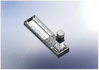
Linear modules · CL rack-and-pinion stage series
CL170CL170 rack-and-pinion stage
Gears and racks are available in different specifications and quality options to suit your requirements.
CL170 · Rack and pinion slide tables
Rack-and-pinion slide tables use gear engagement to drive a linear axis. Compare travel, gear lead and the available drive and mounting arrangement for the task.
Comparing CL170
For CL170, compare these listed entries: Gear lead: 166 mm;Stroke range: 100-4000 mm. Check overhang moments and the load position with the model dimensions. The rail and drive layout must fit the required travel and support structure.
Parameters and where they apply
| Reduction ratio () | Maximum speed (mm/s) | Horizontal load (kg) | Vertical load (kg) | Rated thrust (N) |
|---|---|---|---|---|
| 20:1 | 415 | 105 | 40 | 945 |
| 10:1 | 830 | 75 | 30 | 480 |
| 7:1 | 1185 | 65 | 15 | 240 |
| 5:1 | 1660 | 60 | 10 | 200 |
Stroke over600mm may cause resonance. The source asks for maximum operating-speed confirmation; the overhang tables are printed in mm, not mm/s.
| Gear lead Current technical model | 166 mm |
|---|---|
| Motor power Current technical model | 750 W |
| Rated torque Current technical model | 1.32 Nm |
| Stroke interval Current technical model | 100 mm |
| Movement distance Current technical model | 100-4000 mm |
| Motor installation reference 750 | BD: motor direct position; BL: motor outside left; BR: motor outside right; BM: motor outside lower. These are source ordering/installation references, not a listed configuration. |
| Operating condition 750 | Stroke over600mm may cause resonance. The source asks for maximum operating-speed confirmation; the overhang tables are printed in mm, not mm/s. |
| Ordering example (reference) 750 | CL170-L166-S4000-I5-P750W-B |
| Overhang MP 750 | 1034 N.m |
| Overhang MR 750 | 908 N.m |
| Overhang MY 750 | 1032 N.m |
| Allowable overhang reference 750 | Source allowable-overhang diagrams and installation tables (unit:mm), physical71 left, printed141. The 0°/45°/90° headings are overhang/use references, not motor mounting direction or replacement speed ratings. |
| Repeatability (as printed) Extra printed/source text is preserved; no more precise numerical grade is inferred. · 750 | ±0.04.那 mm |
Additional specifications
| Body width | 170 mm |
|---|
Allowable overhang distances · wall · original p.141
| Printed ratio/load condition | 0°(mm) | 45°(mm) | 90°(mm) |
|---|---|---|---|
| ratio 5:1 · 25kg | 979 mm | 460 mm | 431 mm |
| ratio 5:1 · 45kg | 682 mm | 312 mm | 300 mm |
| ratio 5:1 · 65kg | 566 mm | 203 mm | 171 mm |
| ratio 6:1 · 30kg | 1095 mm | 660 mm | 550 mm |
| ratio 6:1 · 50kg | 730 mm | 335 mm | 325 mm |
| ratio 6:1 · 75kg | 580 mm | 215 mm | 195 mm |
| ratio 10:1 · 50kg | 1212 mm | 478 mm | 369 mm |
| ratio 10:1 · 65kg | 1130 mm | 384 mm | 335 mm |
| ratio 10:1 · 80kg | 973 mm | 263 mm | 220 mm |
| ratio 20:1 · 70kg | 911 mm | 400 mm | 365 mm |
| ratio 20:1 · 90kg | 622 mm | 249 mm | 197 mm |
| ratio 20:1 · 110kg | 464 mm | 176 mm | 110 mm |
Original distance reference(mm); no replacement speed, sellable configuration or angular operating rating is inferred. Blank cells are not zero.
Exact original embedded image981 read; distance6:1 vs main7:1 retained. The horizontal and vertical tables on this supplied PDF are obscured by malformed oversized text and remain pending; no CL210 borrowing.
Talk to HTROBOT
- Emailemmy@htrobot.com
- Phone+86 152 0225 5004
- Alibaba storeVisit our Alibaba store