
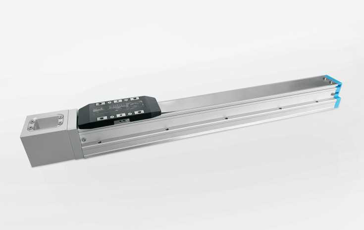
Linear modules · Integrated linear module
MTH5Integrated linear module KTH5
MTH5 belongs to Integrated linear module in the Linear modules catalog.
MTH5 · Ball screw linear modules
A screw-driven linear module converts rotary drive into carriage travel. For a positioning axis, compare screw lead, usable stroke and the installation space for the carriage and motor.
Comparing MTH5
For MTH5, compare these listed entries: Maximum stroke: 800 mm;Motor power: 100 W. Read positioning, load and speed under the same lead and installation conditions. For vertical motion, include holding and brake requirements in the axis proposal.
Parameters and where they apply
| Ball-screw lead (mm) | Maximum speed · 3000 rpm (mm/s) | Horizontal load (kg) | Vertical load (kg) | Rated thrust (N) |
|---|---|---|---|---|
| 5 | 250 | 30 | 10 | 341 |
| 10 | 500 | 15 | 5 | 170 |
| 20 | 1000 | 10 | 2.5 | 85 |
Stroke over600mm requires lower speed; replacement speed ratings are not printed.
| Ball-screw specification Current technical model | 12 mm |
|---|---|
| Maximum speed Current technical model | 1000 mm/s |
| Maximum stroke Current technical model | 800 mm |
| Motor power Current technical model | 100 W |
| Ball screw diameter 100 | 12 mm |
| Motor installation reference 100 | BC: outside; BL: left; BR: right; BM: lower. Source ordering reference only. |
| Power output (table condition) 100 | 100 W |
| Ordering example (reference) 100 | MTH5-L05-500-BC-F0-10-B-C4 |
| Overhang MP 100 | 105 N.m |
| Overhang MR 100 | 150 N.m |
| Overhang MY 100 | 105 N.m |
| Repeatability C · 100 | ±0.01 mm |
| Repeatability P · 100 | ±0.008 mm |
| Sensor ordering reference 100 | C4:672/674 photoelectric switch; E5:not supplied. No outside/inside or motor-direction mapping is inferred. |
| Original accuracy code reference 100 | Main table C±0.01/P±0.008; ordering code L±0.01/P±0.008. The original code letters are retained, not merged. |
| Stroke increment 100 | 50 mm |
| Stroke range 100 | 50–800 mm |
Talk to HTROBOT
- Emailemmy@htrobot.com
- Phone+86 152 0225 5004
- Alibaba storeVisit our Alibaba store